10
10-85
MULTIJUNCTION TIMERS
10.3 TOP (Output-Related 16-Bit Timer)
32180 Group User’s Manual (Rev.1.0)
H'FFFF
H'0000
H'FFF8
H'(FFF0+0014)
H'0004
H'FFF0
H'0014
H'FFF8
H'FFFF
Data inverted
by enable
Data inverted
by underflow
H'(FFF8-1)
Counter
Count clock
Correction register
F/F output
TOP interrupt request
due to underflow
Enable bit
Note: • This diagram does not show detailed timing information.
Reload register
Write to the
correction register
Enabled
(by writing to the enable bit
or by external input)
Disabled
(by underflow)
Undefined
value
Actual count after overflow
Overflow occurs
Undefined
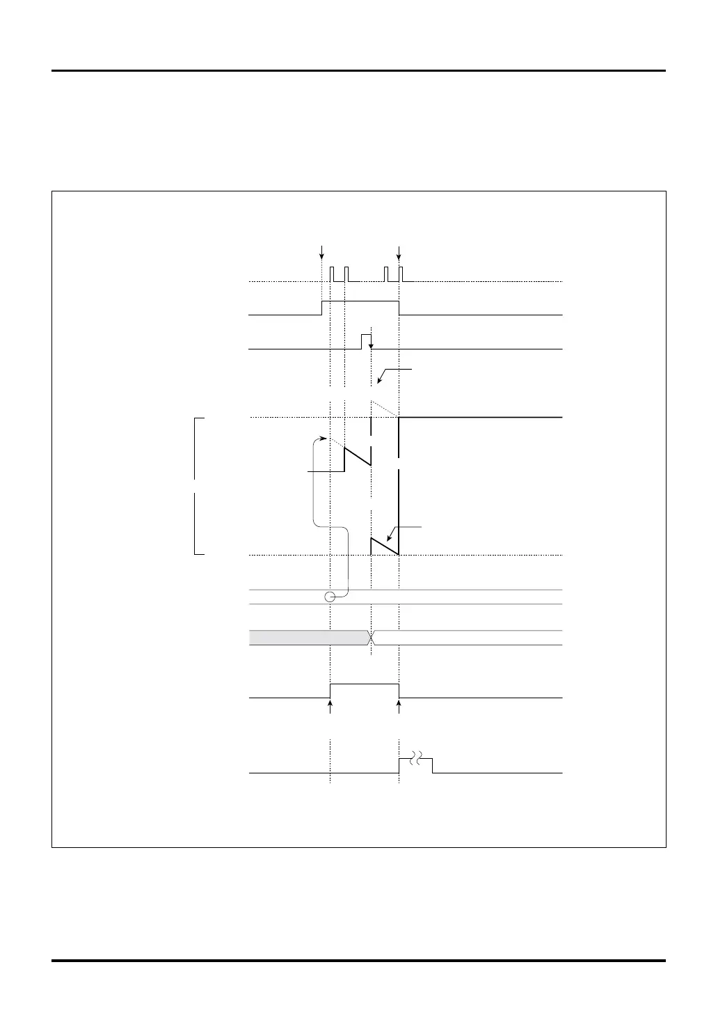
Figure 10.3.11 Example of an Operation in TOP Single-shot Output Mode Where Count Overflows Due to Correction
In the example below, the reload register is initially set to H’FFF8. When the timer starts, the reload register
value is loaded into the counter, letting it start counting down. In the diagram below, the value H’0014 is
written to the correction register when the counter has counted down to H’FFF0. As a result of this correction,
the count overflows to H’0004 and the counter fails to count correctly. Also, an interrupt request is generated
for an erroneous overflowed count.

 Loading...


