10
10-87
MULTIJUNCTION TIMERS
10.3 TOP (Output-Related 16-Bit Timer)
32180 Group User’s Manual (Rev.1.0)
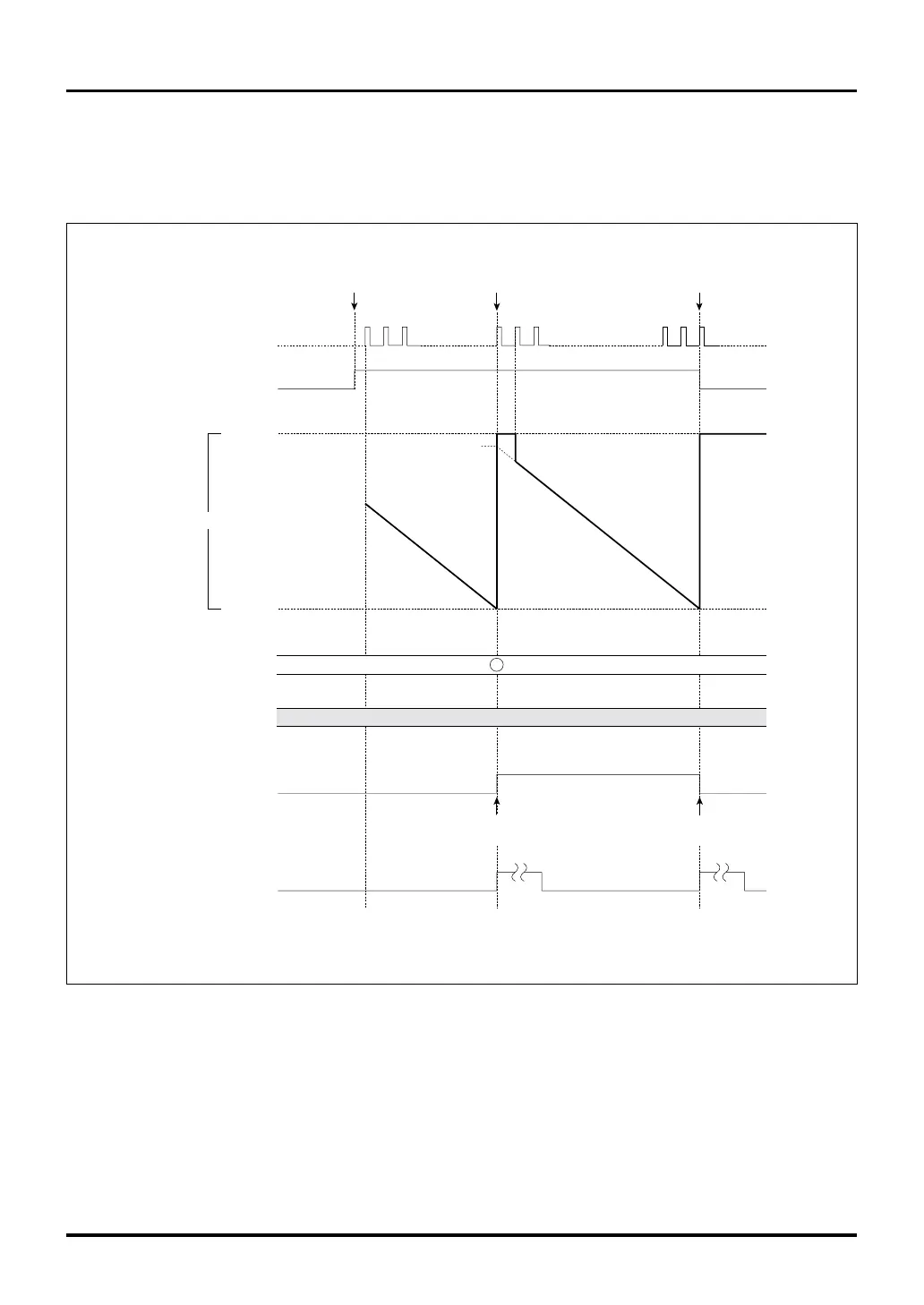
In the example below, the counter and the reload register are initially set to H’A000 and H’F000, respectively.
When the timer is enabled, the counter starts counting down and when it underflows after reaching the
minimum count, the counter is loaded with the content of the reload register and continues counting down.
The counter stops when it underflows second time.
Figure 10.3.13 Typical Operation in TOP Delayed Single-shot Output Mode
H'FFFF
H'0000
Underflow
(first time)
Count down from the
counter's set value
H'A000
Underflow
(second time)
H'F000
Count down from the
reload register's
set value
H'(F000-1)
(Unused)
H'FFFF
H'F000
Data inverted
by underflow
Data inverted
by underflow
Count clock
Correction register
Enabled
(by writing to the enable bit
or by external input)
F/F output
TOP interrupt request
due to underflow
Enable bit
Note: • This diagram does not show detailed timing information.
Reload register
Counter

 Loading...


