1
1-19
OVERVIEW
32180 Group User’s Manual (Rev.1.0)
1.4 Pin Assignments
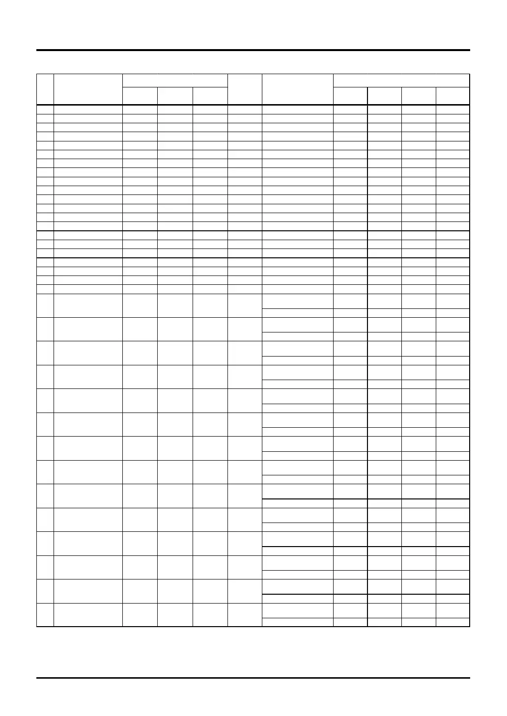
Table 1.4.1 Pin Assignments of the M32180F8VFP/TFP (5/6)
Pin State When Reset
Port
Other than
port
Other than
port
Function Type
State during
reset
State at reset
release
176 P86/RXD1 P86 RXD1 - Input/output P86 Input Hi-z Hi-z
177 P85/TXD1 P85 TXD1 - Input/output P85 Input Hi-z Hi-z
178 P84/SCLKI0/SCLKO0 P84 SCLKI0 SCLKO0 Input/output P84 Input Hi-z Hi-z
179 P83/RXD0 P83 RXD0 - Input/output P83 Input Hi-z Hi-z
180 P82/TXD0 P82 TXD0 - Input/output P82 Input Hi-z Hi-z
181 P174/TXD2 P174 TXD2 - Input/output P174 Input Hi-z Hi-z
182 P175/RXD2 P175 RXD2 - Input/output P175 Input Hi-z Hi-z
183 P176/TXD3 P176 TXD3 - Input/output P176 Input Hi-z Hi-z
184 P177/RXD3 P177 RXD3 - Input/output P177 Input Hi-z Hi-z
185 P173/TIN25 P173 TIN25 - Input/output P173 Input Hi-z Hi-z
186 P172/TIN24 P172 TIN24 - Input/output P172 Input Hi-z Hi-z
187 FP - FP - Input FP Input Hi-z Hi-z
188 MOD0 - MOD0 - Input MOD0 Input Hi-z Hi-z
189 MOD1 - MOD1 - Input MOD1 Input Hi-z Hi-z
190 EXCVDD - EXCVDD - - EXCVDD - - -
191 VSS - VSS - - VSS - - -
192 EXCVCC - EXCVCC - - EXCVCC - - -
193 VDDE - VDDE - - VDDE - - -
194 VSS - VSS - - VSS - - -
195 VCCE - VCCE - - VCCE - - -
196 VCC-BUS - VCC-BUS - - VCC-BUS - - -
During single-chip and
external extension modes
P17 Input Hi-z Hi-z
During processor mode DB15 Input/output Hi-z Hi-z
During single-chip and
external extension modes
P16 Input Hi-z Hi-z
During processor mode DB14 Input/output Hi-z Hi-z
During single-chip and
external extension modes
P15 Input Hi-z Hi-z
During processor mode DB13 Input/output Hi-z Hi-z
During single-chip and
external extension modes
P14 Input Hi-z Hi-z
During processor mode DB12 Input/output Hi-z Hi-z
During single-chip and
external extension modes
P13 Input Hi-z Hi-z
During processor mode DB11 Input/output Hi-z Hi-z
During single-chip and
external extension modes
P12 Input Hi-z Hi-z
During processor mode DB10 Input/output Hi-z Hi-z
During single-chip and
external extension modes
P11 Input Hi-z Hi-z
During processor mode DB9 Input/output Hi-z Hi-z
During single-chip and
external extension modes
P10 Input Hi-z Hi-z
During processor mode DB8 Input/output Hi-z Hi-z
During single-chip and
external extension modes
P07 Input Hi-z Hi-z
During processor mode DB7 Input/output Hi-z Hi-z
During single-chip and
external extension modes
P06 Input Hi-z Hi-z
During processor mode DB6 Input/output Hi-z Hi-z
During single-chip and
external extension modes
P05 Input Hi-z Hi-z
During processor mode DB5 Input/output Hi-z Hi-z
During single-chip and
external extension modes
P04 Input Hi-z Hi-z
During processor mode DB4 Input/output Hi-z Hi-z
During single-chip and
external extension modes
P03 Input Hi-z Hi-z
During processor mode DB3 Input/output Hi-z Hi-z
During single-chip and
external extension modes
P02 Input Hi-z Hi-z
During processor mode DB2 Input/output Hi-z Hi-z
Input/output
- Input/output
- Input/output
Symbol Type Condition
197 P17/DB15 P17 DB15
Pin
No.
Function
-
198 P16/DB14 P16 DB14
- Input/output
199 P15/DB13
200 P14/DB12 P14 DB12
P15 DB13
201 P13/DB11 P13 DB11
- Input/output
202 P12/DB10 P12 DB10
- Input/output
- Input/output
- Input/output
203 P11/DB9
204 P10/DB8 P10 DB8
P11 DB9
205 P07/DB7 P07 DB7
206 P06/DB6 P06 DB6
Input/output
- Input/output
- Input/output
-
- Input/output
P05 DB5
- Input/outputP04 DB4
- Input/output
209 P03/DB3
210 P02/DB2 P02 DB2
P03 DB3
207 P05/DB5
208 P04/DB4

 Loading...


