10
10-146
MULTIJUNCTION TIMERS
10.7 TID (Input-Related 16-Bit Timer)
32180 Group User’s Manual (Rev.1.0)
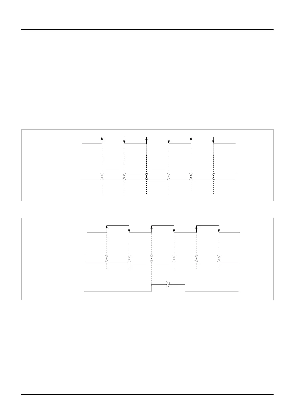
(2) Event count mode
In event count mode, the timer uses an external input signal (TIN24, TIN26 or TIN28) as the clock source for
the counter.
Note: • TIN25, TIN27 and TIN29 cannot be used as the clock source for the counter.
By detecting the rising and falling edges of the external input signal (TIN24, TIN26 or TIN28), the timer
generates clock pulses synchronized to the microcomputer’s internal clock. When after setting the counter
the timer is enabled (by writing to the enable bit in software), the counter starts counting up from the set count
value synchronously with the generated clock. An interrupt request can be generated by a counter overflow.
To stop the counter, disable count by writing to the enable bit in software or fix the external input signal either
"high" or "low".
TIN24
(TIN26, TIN28)
Counter value 7FFF 8000 8001 8002 8003 8004
Figure 10.7.4 Typical Operation in TID Event Count Mode (Basic Operation)
Figure 10.7.5 Typical Operation in TID Event Count Mode (when Overflow Occurs)
TIN24
(TIN26, TIN28)
Counter value
FFFE
FFFF
0000 0001 0002
0003
TID interrupt request
due to overflow
FFFD

 Loading...


