10
10-149
MULTIJUNCTION TIMERS
10.7 TID (Input-Related 16-Bit Timer)
32180 Group User’s Manual (Rev.1.0)
(4) Up/down event count mode
In up/down event count mode, the timer uses one of two-channel external input signals (TIN24, TIN26 or
TIN28) as the clock source for the counter and the other (TIN25, TIN27 or TIN29) as an up/down select
signal.
The counter is switched between up-count and down-count depending on the status of the up/down select
input signal. By detecting the rising and falling edges of the external input signal selected as the clock source,
the timer generates clock pulses synchronized to the microcomputer’s internal clock. When after setting the
counter the timer is enabled, the counter starts counting up or down synchronously with the generated clock.
The count direction is determined by the level of the up/down select input signal (see Table 10.7.3). An
interrupt request can be generated when the counter underflows or overflows.
To stop the counter, disable count by writing to the enable bit in software or fix the external input signal
selected as the clock source either "high" or "low".
Note that TIN25, TIN27 and TIN29 cannot be used as the clock source.
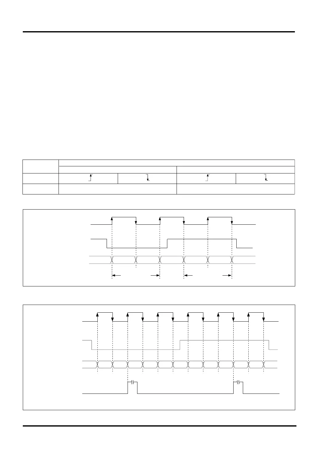
Table 10.7.3 Count Direction during Up/Down Event Count Mode
TIN24
(TIN26, TIN28)
TIN25
(TIN27, TIN29)
Input
Up-count Down-count
Count Direction
Low level High level
Figure 10.7.9 Up/Down Count Operation
Figure 10.7.10 Up/Down Count Operation (Interrupt Request Timing)
TIN25
(TIN27, TIN29)
Counter value 7FFF 7FFF8000 8001 8002 8001
8000
Up-count Down-count
TIN24
(TIN26, TIN28)
FFFD FFFE FFFF 0000 0001 0002 0003 0002 0001 0000 FFFF FFFE FFFD
TIN24
(TIN26, TIN28)
TIN25
(TIN27, TIN29)
Counter value
TID output interrupt
request due to
overflow or underflow

 Loading...


