12
12-41
Serial I/O
12.6 Transmit Operation in UART Mode
32180 Group User's Manual (Rev.1.0)
Table 12.6.1 Transfer Data in UART Mode
Bit Name Content
ST (start bit) Indicates the beginning of data transmission. This is a low-level signal of a one bit
period, which is added immediately preceding the transmit data.
Bits 0–8 (character bits) Transmit/receive data transferred via serial I/O. In UART mode, 7, 8 or 9 bits of data
can be transmitted/received.
PAR (parity bit) Added to the transmit/receive character. When parity is enabled, parity is
automatically set in such a way that the number of 1’s in the character including the
parity bit itself is always even or odd as selected by the even/odd parity select bit.
SP (stop bit) Indicates the end of data transmission, which is added immediately following the
character (or if parity is enabled, immediately following the parity bit). The stop bit
can be chosen to be one bit or two bits long.
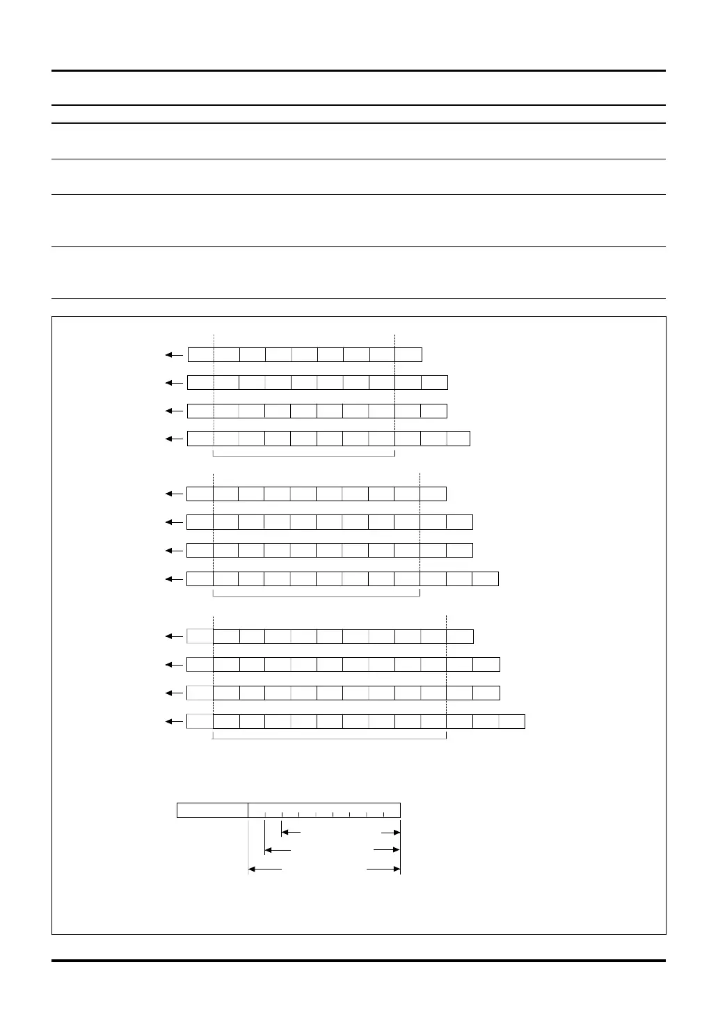
Figure 12.6.2 Selectable Data Formats during UART Mode
ST b7 b6 b5 b4 b3 b2 b1 b0
PA R S P S P
ST b7 b6 b5 b4 b3 b2 b1 b0
PA R S P
ST b7 b6 b5 b4 b3 b2 b1 b0 SPSP
ST b7 b6 b5 b4 b3 b2 b1 b0 SP
LSB
MSB
8-bit character
ST b7 b6 b5 b4 b3 b2 b1 SP
SPPA R
ST b7 b6 b5 b4 b3 b2 b1 SP
PA R
ST b7 b6 b5 b4 b3 b2 b1 SP
SP
ST b7 b6 b5 b4 b3 b2 b1
SP
LSB MSB
7-bit character
9-bit character
ST
b7 b6 b5 b4 b3 b2 b1 b0
PA R S P S P
ST b7 b6 b5 b4 b3 b2 b1 b0
PA R S P
ST
b7 b6 b5 b4 b3 b2 b1 b0 SPSP
ST
b7 b6 b5 b4 b3 b2 b1 b0
SP
LSB
MSB
b8
b8
b8
b8
Bits 0-7: Character (data) bits
SP: Stop bit
ST: Start bit
PAR: Parity bit
b0
b7 b8
b15
7-bit character
8-bit character
9-bit character
SIO Transmit Buffer Register
SIO Receive Buffer Register
Notes: • The high-order bits of the selected character length in the SIO Receive Buffer Register are fixed to "0".
• The data bit numbers (bn) above indicate bit numbers in a data list, and not the register bit numbers (bn).

 Loading...


