14
14-2
REAL TIME DEBUGGER (RTD)
32180 Group User’s Manual (Rev.1.0)
14.1 Outline of the Real-Time Debugger (RTD)
The Real-Time Debugger (RTD) is a serial I/O through which to read or write to any location in the entire area of
the internal RAM by using commands from outside the microcomputer. Because data transfers between the RTD
and internal RAM are performed via a dedicated internal bus independently of the M32R-FPU, RTD operation can
be controlled without the need to stop the M32R-FPU.
Table 14.1.1 Outline of the Real-Time Debugger (RTD)
Item Description
Transfer method Clock-synchronous serial I/O
Generation of transfer clock Generated by external host
RAM access area Entire area of the internal RAM (controlled by A16–A29)
Transmit/receive data length 32 bits (fixed)
Bit transfer sequence LSB first
Maximum transfer rate 2 Mbits/second
Input/output pins 4 pins (RTDTXD, RTDRXD, RTDACK, RTDCLK)
Number of commands Following five functions
• Monitor continuously
• Output real-time RAM content
• Forcibly rewrite RAM content (with verify)
• Recover from runaway condition
• Request RTD interrupt
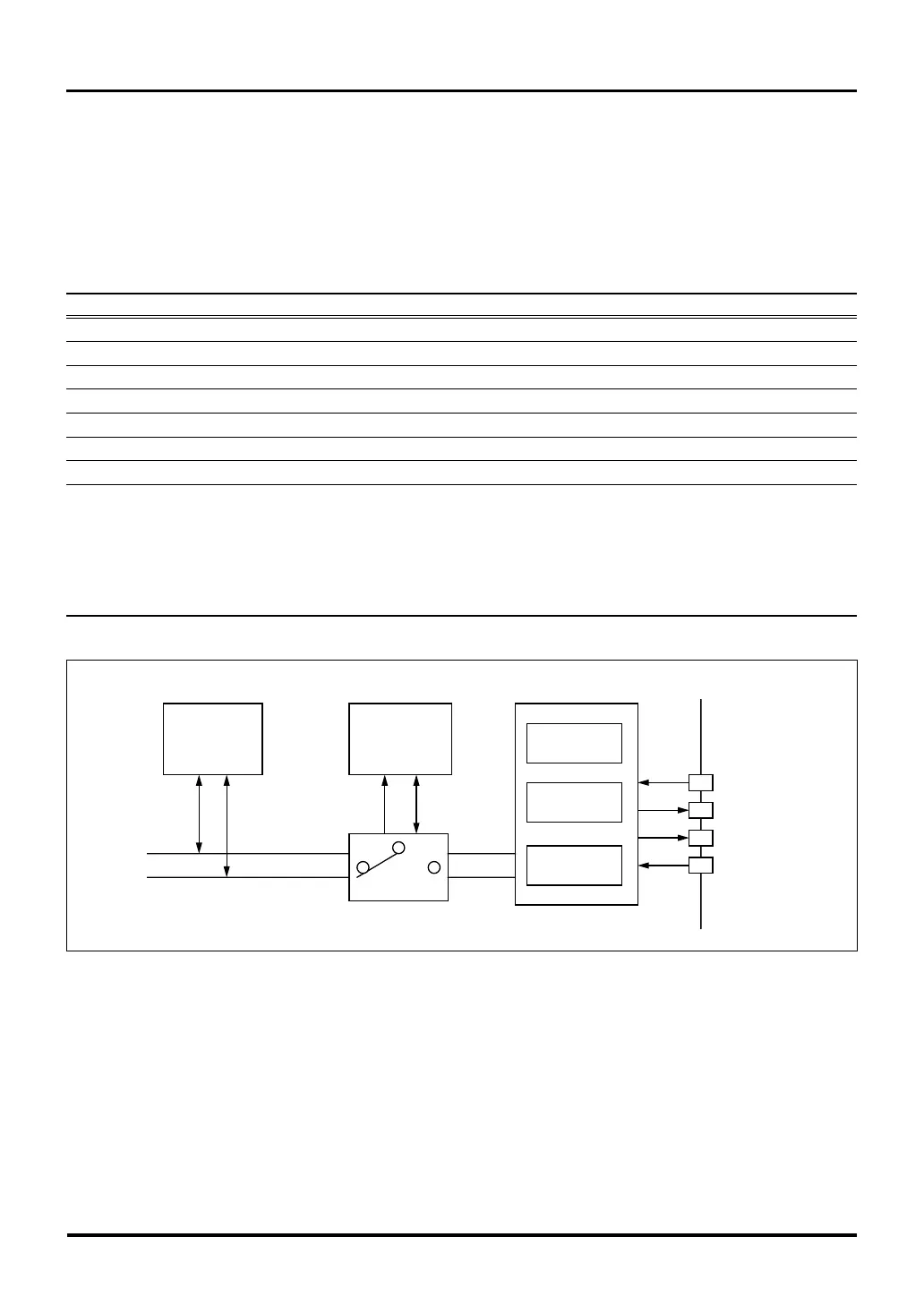
Figure 14.1.1 Block Diagram of the Real-Time Debugger (RTD)
14.1 Outline of the Real-Time Debugger (RTD)
Control Circuit
Commands
Data
Data
Address
Address Data
RTD Control Circuit
Entire RAM area
CPU
Address Data
Bus Switching Circuit
RTDCLKRTDCLK
RTDACK
RTDTXD
RTDRXD

 Loading...


