16
16-15
WAIT CONTROLLER
16.3 Typical Operation of the Wait Controller
32180 Group User’s Manual (Rev.1.0)
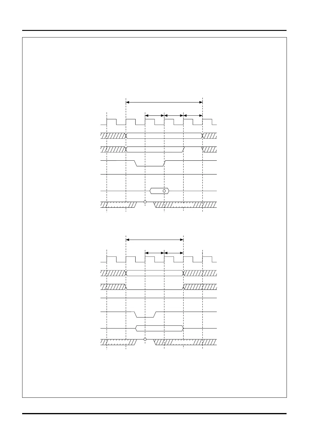
Figure 16.3.10 Read/Write Timing (Internal 2 Wait States + Recovery and Idle Cycles Added)
Read
Read (4 cycles)
BCLK
A11–A30
CS0#–CS3#
BHW#, BLW#
DB0–DB15
WAIT#
RD#
"H"
Note 1: For details about the Bus Mode Control Register, see Section 15.2.3, "Bus Mode Control Register."
Note 2: For details about the CS Area Wait Control Register, see Section 16.2.1, "CS Area Wait Control Registers."
Notes: • Circles in the above diagram indicate the sampling timing.
• No idle cycles are added after the write cycle.
Internal
1 wait state
Recovery
cycle
(Don't Care)
"H"
(Don't Care)
Write
Write (3 cycles)
BCLK
A11–A30
CS0#–CS3#
BHW#, BLW#
DB0–DB15
WAIT#
RD#
"H"
Internal
1 wait state
(Don't Care)
"H"
(Don't Care)
Idle
cycle
Recovery
cycle
Bus Mode Control Register (Note 1)
BUSMOD bit = 0 (WR signal separated)
CS Area Wait Control Register (Note 2)
WTCSEL bit = 001 (1 wait)
SWAIT bit = 0 (without strobe wait)
RECOV bit = 1 (with recovery cycle)
IDLE bit = 1 (with idle cycle)

 Loading...


