19
19-3
JTAG
32180 Group User's Manual (Rev.1.0)
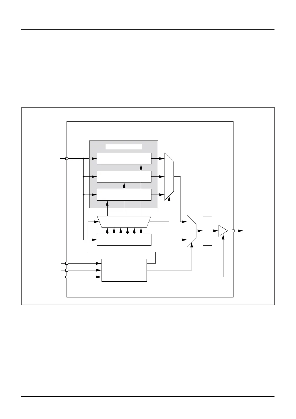
Figure 19.2.1 Configuration of the JTAG Circuit
19.2 Configuration of the JTAG Circuit
The JTAG circuit included in the M32R/ECU consists of several circuit blocks as shown in Figure 19.2.1.
• Instruction register to hold the instruction code that is fetched through the boundary-scan path
• A set of registers which are accessed through the boundary-scan path (boundary-scan register, bypass regis-
ter and ID code register)
• Test access port (abbreviated TAP) controller to control the JTAG unit’s state transition
• Control logic to select input, output, etc.
19.2 Configuration of the JTAG Circuit
JTCK
JTMS
JTRST
TAP Controller
Instruction Register (6-bit)
(JTAGIR)
Decoder
JTDO
ID Code Register
(JTAGIDR)
Bypass Register
(JTAGBPR)
Boundary Scan Register
(JTAGBSR)
JTDI
Data register set
Buffer
Output selection
Output selection
M32R/ECU

 Loading...


