19
19-7
JTAG
32180 Group User's Manual (Rev.1.0)
Select-DR-Scan
Test-Logic-Reset
Run-Test/Idle
0
1
0
Capture-DR
0
Shift-DR
0
Exit1-DR
1
Pause-DR
0
Exit2-DR
1
Update-DR
1
0
0
1 0
1
1
0
Select-IR-Scan
Capture-IR
0
Shift-IR
0
Exit1-IR
1
Pause-IR
0
Exit2-IR
1
Update-IR
1
0
0
1 0
1
1
0
11
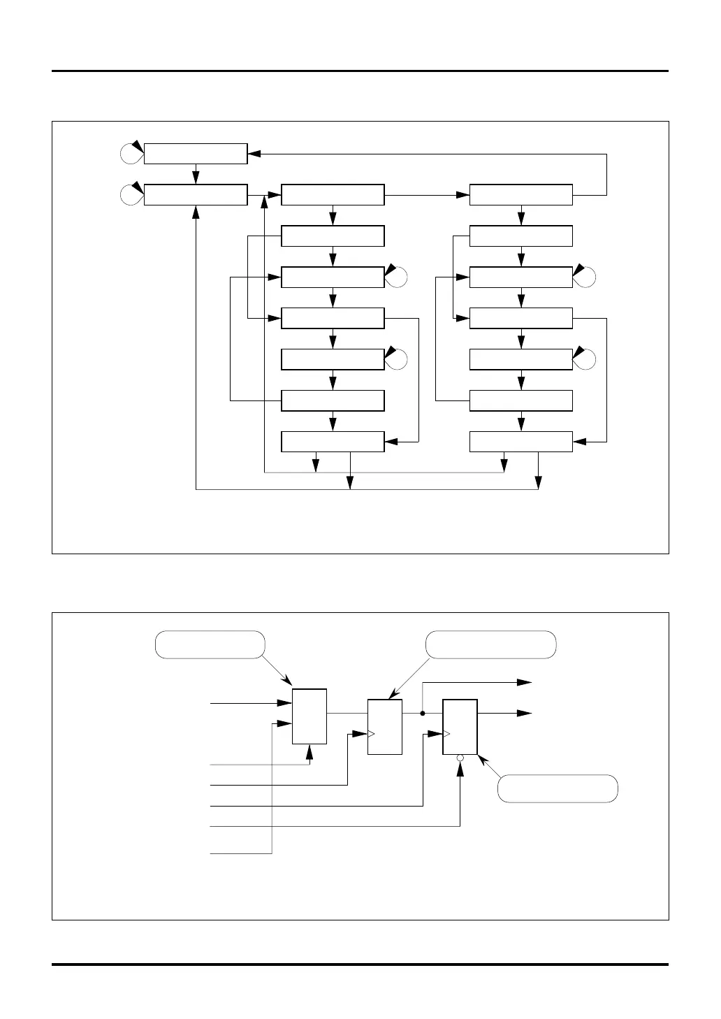
Note: • The values (0 or 1) in this diagram denote the state of JTMS input signal.
1
Figure 19.4.1 TAP Controller State Transition
The state transition of the TAP Controller and the basic configuration of the JTAG related registers are shown below.
Data input
G
0
1
D
T
Q D
T
R
Q
Shift-DR or Shift-IR
Clock-DR or Clock-IR
Update-DR or Update-IR
Test reset
From the preceding cell
To the next cell
Data output
Parallel output stage
Shift register stageInput multiplexer
Note: • This diagram only shows the basic configuration; not all DR and IR are configured the same way as shown here.
Figure 19.4.2 Basic Configuration of the JTAG Related Registers
19.4 Basic Operation of JTAG

 Loading...


