20
20-8
POWER SUPPLY CIRCUIT
32180 Group User's Manual (Rev.1.0)
20.3 Power-Off Sequence
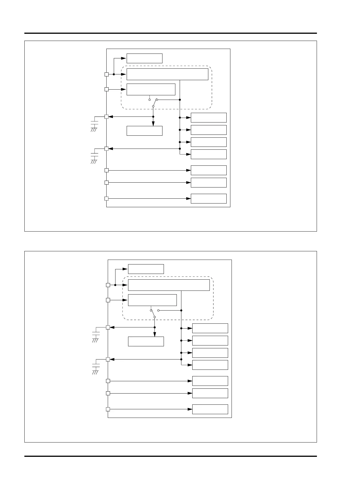
Figure 20.3.4 Microcomputer Ready to Operate State (VCCE = 5.0 V or 3.3 V)
VCCE
32180
OSC-VCC
AVCC
VCC-BUS
VDDE
EXCVDD
VDC
EXCVCC
1–10 µF
CPU
PLL
RAM
1–10 µF
(Note 1)
0V
3.0–5.5V
0V
0V
0V
Note 1: Make sure this voltage is the same as VCCE.
Note 2: During RAM backup mode, it automatically switches to the sub-VDC for low-power operation.
I/O Control Circuit
Internal Voltage Generator Circuit
Main VDC
Backup Voltage Generator Circuit
Sub-VDC
(Note 2)
Peripheral Circuit
Flash Memory
Oscillator Circuit
A-D Converter Circuit
External Bus
Figure 20.3.5 SRAM Data Backup State (VCCE = 5.0 V or 3.3 V)
VCCE
32180
OSC-VCC
AVCC
VCC-BUS
VDDE
EXCVDD
VDC
EXCVCC
1–10 µF
I/O Control Circuit
CPU
Peripheral Circuit
Flash Memory
PLL
Oscillator Circuit
A-D Converter Circuit
External Bus
RAM
Internal Voltage Generator Circuit
Main VDC
Backup Voltage Generator Circuit
Sub-VDC
1–10 µF
(Note 1)
5 V or 3.3 V
5 V or 3.3 V
5 V or 3.3 V
5 V or 3.3 V
5 V or 3.3 V
(Note 2)
Note 1: Make sure this voltage is the same as VCCE.
Note 2: When the microcomputer is ready to operate, it automatically switches to the main VDC.

 Loading...


