Appendix 3
Appendix 3-3
32180 Group User's Manual (Rev. 1.0)
PROCESSING OF UNUSED PINS
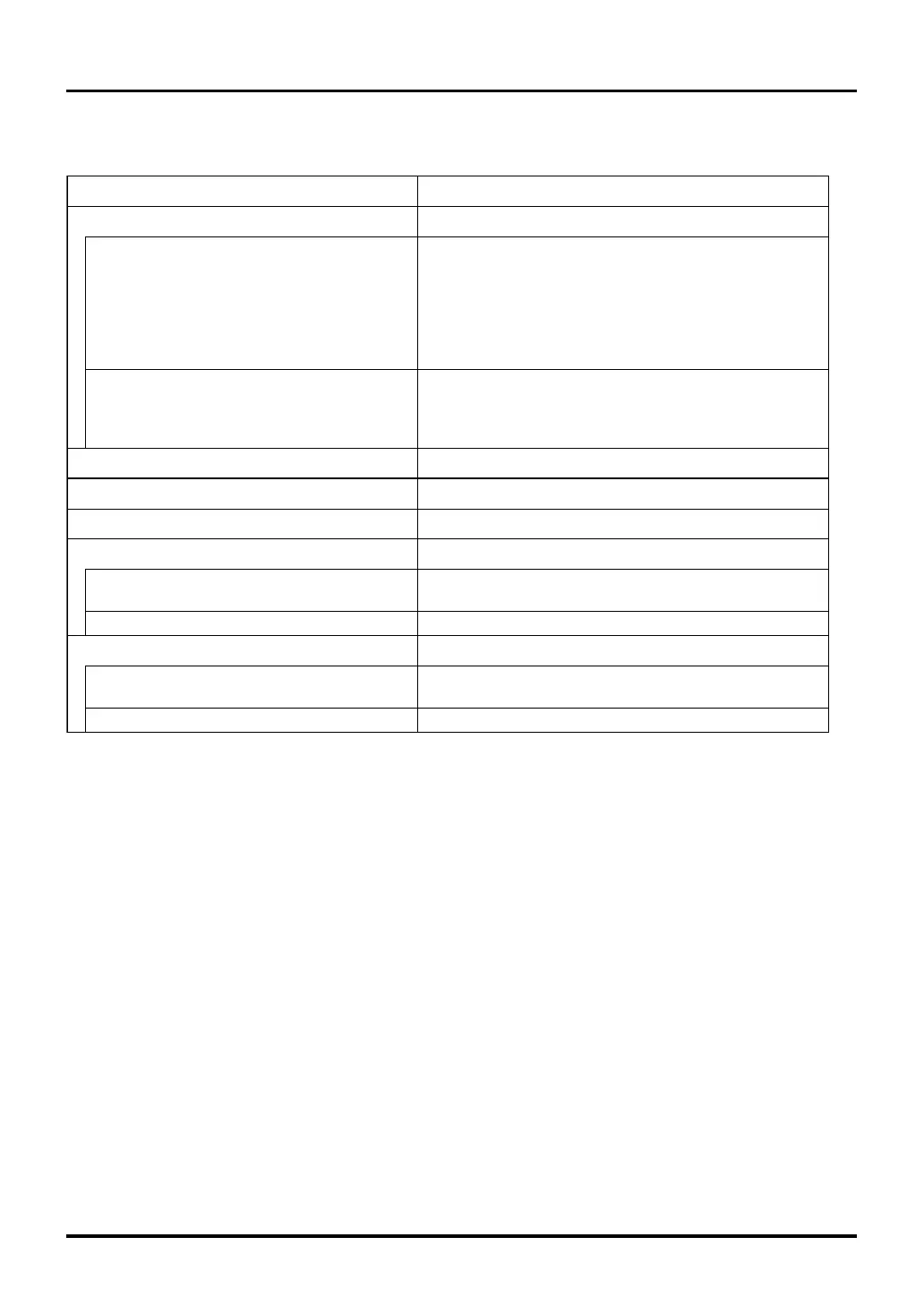
(2) When operating in external extension mode
Table 3.1.2 Example Processing of Unused Pins during External Extension Mode (Note 1)
Pin Name
P61–P63, P65–P67,
P74–P77, P82–P87, P93–P97,
P100–P107, P110–P117, P124–P127,
P130–P137, P140–P147, P150–P157,
P160–P167, P172–P177, P180–P187,
P190–P197, P200–P203, P210–P217,
P220–P223
Processing
XOUT (Note 4)
AD0IN0–AD0IN15, AD1IN0–AD1IN15,
AVREF0, AVREF1, AVSS0, AVSS1
Leave open
Connect to VCCEAVCC0, AVCC1
JTAG
JTDO, JTMS, JTDI, JTCK
JTRST
Pull high to VCCE or low to VSS via a 0-100 kΩ resistor
Pull low to VSS via a 0-100 kΩ resistor
Connect to VSS
A-D converter
Note 1: Process the unused pins in the shortest wiring length possible (within 20 mm) from the microcomputer pins.
Note 2: If any port is set for output mode and left open, care should be taken because the port remains set for input
before it is changed for output in a program after being reset. Therefore, the voltage level at the pin is instable,
and the power supply current tends to increase while the port remains set for input. Because it is possible that
the content of the port direction register will inadvertently be altered by noise or noise-induced runaway,
higher reliability may be obtained by periodically setting the port direction register back again in a program.
Note, however, that P221 and P223 are input-only ports and do not work as an output port.
Note 3: Make sure that unintended falling edges due to noise, etc. will be not applied. (A falling edge at the SBI# input
causes a system break interrupt to occur.)
Note 4: This is necessary when an external clock is connected to XIN.
BLW#/BLE#, BHW#/BHE#, RD#
Leave open
SBI# (Note 3) Pull low to VSS via a 1 kΩ-10 kΩ resistor
Input/output ports (Note 2)
P00–P07, P10–P17, P20–P27,
P30–P37, P44–P47, P70–P73,
P224–P227
Set the port for input mode and pull each pin low to VSS or
pull high to VCCE via a 1 kΩ-10 kΩ resistor.
Or set the port for output mode and leave the pin open.
Set the port for input mode and pull each pin low to VSS or
pull high to VCC-BUS via a 1 kΩ-10 kΩ resistor.
Or set the port for output mode and leave the pin open.
Appendix 3.1 Example Processing of Unused Pins

 Loading...


