Appendix 4
Appendix 4-24
32180 Group User's Manual (Rev. 1.0)
SUMMARY OF PRECAUTIONS
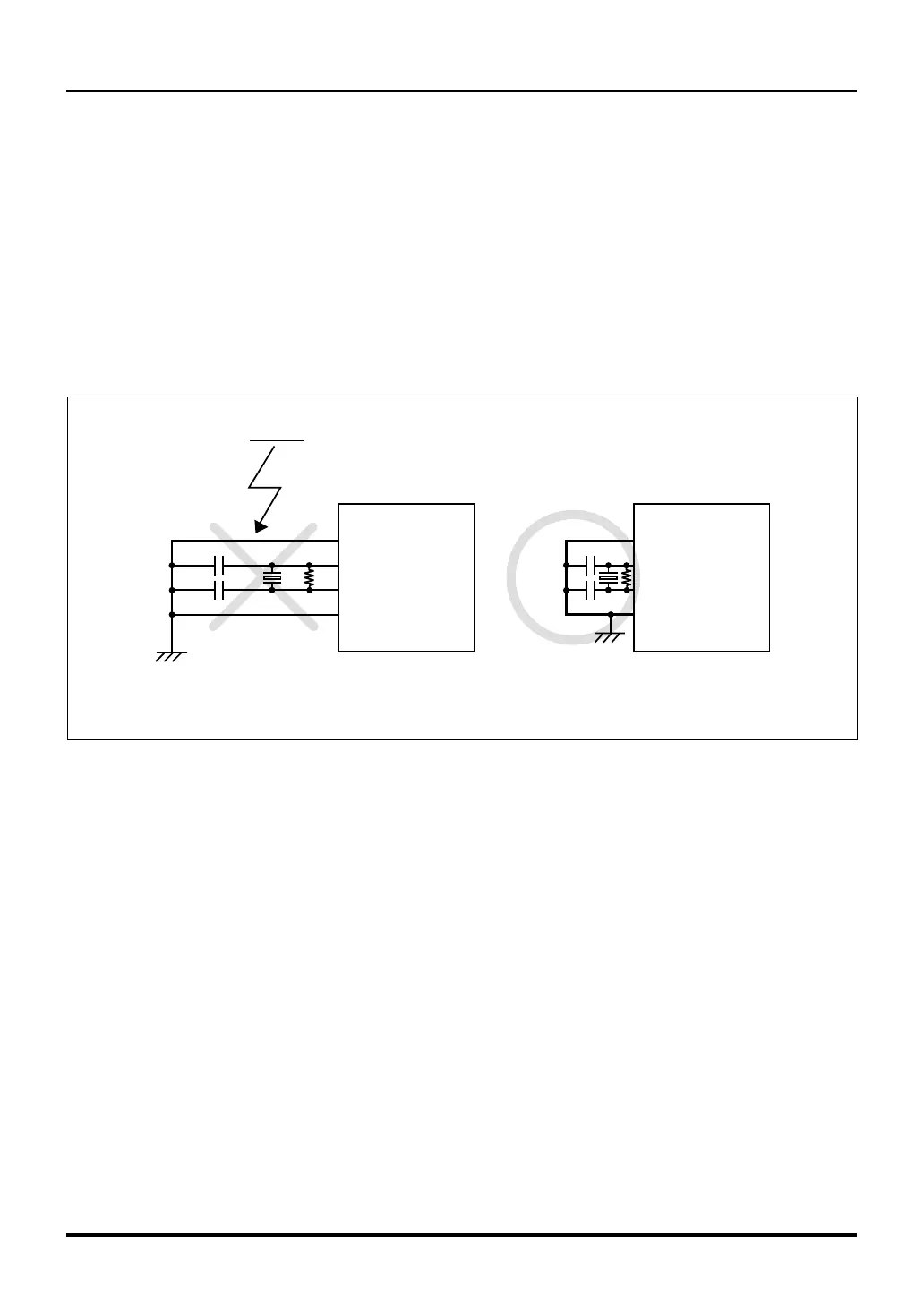
(2) Wiring of clock input/output pins
Use as much thick and short wiring as possible for connections to the clock input/output pins.
When connecting a capacitor to the oscillator, make sure its grounding lead wire and the OSC-VSS pin on the
microcomputer are connected in the shortest distance possible (within 20 mm).
Also, make sure the VSS pattern used for clock oscillation is a large ground plane and is connected to GND.
<Reasons>
The microcomputer operates synchronously with the clock generated by an oscillator circuit. Inclusion of
noise on the clock input/output pins causes the clock waveform to become distorted, which may result in
the microcomputer operating erratically or getting out of control. Furthermore, if a noise-induced poten-
tial difference exists between the microcomputer’s VSS level and that of the oscillator, the clock fed into
the microcomputer may not be an exact clock.
Figure 4.13.2 Example Wiring of Clock Input/Output Pins
OSC-VSS
XIN
XOUT
VSS
Noise
Thick and short wiring
Thin and long wiring
OSC-VSS
XIN
XOUT
VSS
Appendix 4.13 Precautions about Noise
 Loading...


