Appendix 4
Appendix 4-26
32180 Group User's Manual (Rev. 1.0)
SUMMARY OF PRECAUTIONS
Appendix 4.13.3 Processing Analog Input Pin Wiring
Insert a resistor of about 100 to 500Ω in series to the analog signal line connecting to the analog input pin at a
position as close to the microcomputer as possible. Also, insert a capacitor of about 100 pF between the analog
input pin and AVSS pin at a position as close to the AVSS pin as possible.
<Reasons>
The signal fed into the analog input pin (e.g., A-D converter input pin) normally is an output signal from a
sensor. In many cases, a sensor to detect changes of event is located apart from the board on which the
microcomputer is mounted, so that wiring to the analog input pin is inevitably long. Because a long wiring
serves as an antenna which draws noise into the microcomputer, the signal fed into the analog input pin
tends to be noise-ridden. Furthermore, if the capacitor connected between the analog input pin and
AVSS pin is grounded at a position apart from the AVSS pin, noise riding on the ground line may pen-
etrate into the microcomputer via the capacitor.
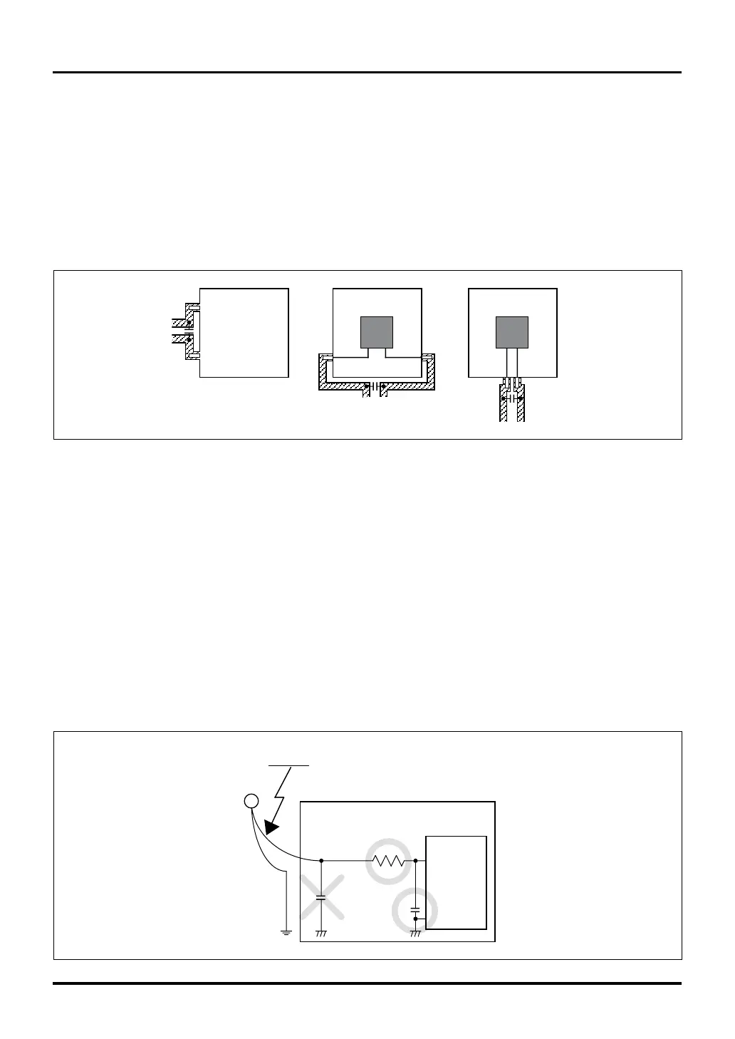
Figure 4.13.6 Example of a Resistor and Capacitor Inserted for the Analog Signal Line
Appendix 4.13.2 Inserting a Bypass Capacitor between VSS and VCC Lines
Insert a bypass capacitor of about 0.1 µF between the VSS and VCC lines. At this time, make sure the require-
ments described below are met.
• The wiring length between the VSS pin and bypass capacitor and that between the VCC pin and bypass
capacitor are the same.
• The wiring length between the VSS pin and bypass capacitor and that between the VCC pin and bypass
capacitor are the shortest distance possible.
• The VSS and VCC lines have a greater wiring width than that of all other signal lines.
Figure 4.13.5 Example of a Bypass Capacitor Inserted between VSS and VCC Lines
VSS
VCC
Chip Chip
VSSVCC
VSS
VCC
Analog
input pin
AVSS
Sensor
Noise
Microcomputer
Appendix 4.13 Precautions about Noise
 Loading...


