3-24 Troubleshooting
7000-TD002A-EN-P – September 2007
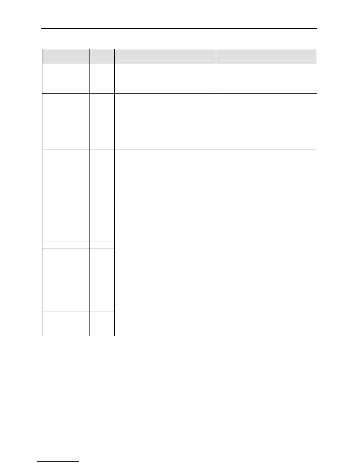
FAULT
MESSAGE
FAULT
CODE
DESCRIPTION RECOMMENDED ACTIONS
Tach Loss 163 This fault is for parallel drives. The signal
from the encoder (tachometer) was lost.
Ensure that the encoder is powered and
connected properly
– Check the tach feedback
– Check if there is any loss of tach
feedback signals.
– Check the PS for Tach signal on ACB
TempFeedback
Loss
(C-Frame only)
73 This fault occurs only if the drive is not
running. The drive has detected missing
temperature feedback from the cooling
system. A missing sensor can be
interpreted as either 0°C or over 100°C, and
both are unrealistic values, so it is
considered a Feedback Loss.
– Verify sensor is completely seated
properly on TFB.
– Measure sensor resistance.
– Verify Fiber Optics are properly seated
on TFB
– Verify the TFB has power
– Replace if necessary.
UPS Fault 62 The drive has detected that either the UPS
is running on low battery or there is an
internal problem with the UPS and the dc
output voltage of the dc/dc converter fed by
the UPS has dropped below 52V.
– Check the UPS and the AC/DC power
supply.
– Investigate what is causing PS dip.
Replace UPS or PS if the problem still
persists.
U1A Offline 246
U1B Offline 252
U1C Offline 258
U4A Offline 249
U4B Offline 255
U4C Offline 261
V3A Offline 248
V3B Offline 254
V3C Offline 260
V6A Offline 251
V6B Offline 257
V6C Offline 263
W2A Offline 247
W2B Offline 253
W2C Offline 259
W5A Offline 250
W5B Offline 256
W5C Offline 262
INVERTER SGCT FAULT
This fault will only occur during the initial
contactor closure and the diagnostic
sequence after a start command. The
inverter monitors the state of the feedback
before a gate pulse is given, and monitors
the feedback after a gate pulse has been
sent. The SGCT has smart diagnostics, so
the feedback may indicate short before
firing, and if the pulse is received and the
device is really shorted, the diagnostic will
toggle the feedback to let you know the
problem is with the device, or the power
supply for that device.
The firmware now completes a diagnostics
sequence immediately after any drive reset,
with the goal of detecting faults before any
destructive action is taken from the next
action
– Complete a resistance check per the
instructions in the manual
– NOTE: SGCTs may not have completely
shorted, and still could read in the kΩ
range – Any devices with low suspect
readings should be changed
– Check the LED status of the SCGT gate
driver card for abnormal readings
– Complete a Gating Test mode check on
the devices
– Verify the associated 20V power supply
is powered and active
– Verify all the power connections to the
SCGT firing card are seated properly

 Loading...


