Workshop
Manual
Rolls Royce Silver
Shadow
8
Bentley
T
Ser~es
Chapter
J
The spring balance reading obtained to initially
rotate the pinion will be high.
It is the lower steady
reading when the pinion is rotating, which indicates
the
pre:loading.
9. If the pre-load is not correct the pinion must
be
extracted from the housing and the adjusting washers
changed
as
necessary to obtain the correct reading.
Adjusting washers are available in a range from
0.105 in. to 0.110 in. (2,66
rnm.
to 2,79 mm.) and
0.1
10 in. to 0.160 in. (2,79
mm.
to 4,06
mm.)
in 0.001
in.
(0,025
mm.)
and 0.005 in. (0,127 mm.) increments
respectively.
Reducing the combined thickness of the washers
will increase the pre-load and increasing the thickness
will
reduce it but, it must
be
noted that very small
changes to the thickness of the washers has a marked
effect on the pre-load figure.
0
K
IW
10. When the pinion has been pre-loaded correctly,
turn over the tab on the lock-washer fitted under the
FIG.
57
STAMPED DIMENSION ON FINAL DRIVE
pinion flange retaining nut.
CASING
between
8
lb. in. and 10 lb.
in.
(0,092 kg.m. and 0,115
kg.m.) and this is best checked using
a
spring balance
pulling on a bolt inserted into one of the holes
in
the
pinion flange.
Note
The holes
in
the pinion flange
are
1.875 in.
(4,762
cm.)
away from the centre of the
pinion
and
therefore
if
this method
is
used
the spring balance reading should
be
between 4.3
Ib.
and
5.3
Ib.
(1,949
kg. and 2,403 kg.).
Final
drive
unit-To
assemble
To assemble the final drive unit reverse the procedure
given for dismantling ensuring that the crown wheel
and pinion are in their correct relative positions and
that there
i?l
the correct amount of backlash between
the two gears.
All
parts
must be cleaned thoroughly prior to
assembly and all bearings, other than new ones,
lubricated.
1.
Before commencing to assemble the final drive
unit, the
stiffening bar
(RH
8032) should be fitted to
0
the
final
drive casing.
2.
Partly screw four
Q
in.
U.N.F.
studs into the
threaded holes in the front of the final drive casing.
It is sufficient to fit these studs
by
hand as they serve
only as location pegs for the pinion housing.
3.
If the pinion nose bearing was removed from the
casing previously, fit the bearing, and the two socket
headed retaining screws, nuts and washers.
Note the dimension stamped on the cast rib, just
above the front flange of the
final drive casing (see
Fig.
J7).
!~157
4.
Place the differential casing in an oven at a
temperature of 80°C
(176°F)
for &oximately
1
hour.
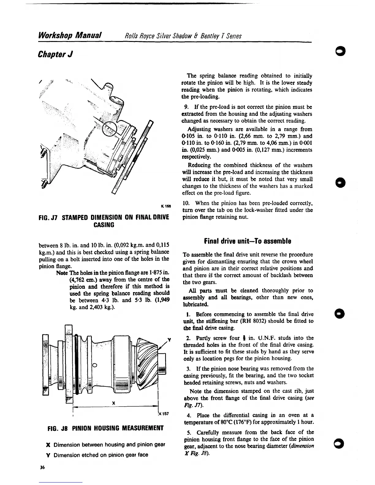
FIG.
J8
PINION HOUSING MEASUREMENT
5. Carefa measure from the back face of the
pinion
housiig front flange to the face of the pinion
X
Dimension between housing and pinion gear
gear, adjacent to the nose bearing diameter
(dimension
0
V
Dimension etched on pinion
gear
face
X
Fig.
58).