Rolls-Royce Silver Shadow
B
Bentley
T
Series
Workshop
Manual
Chapter
M
3.
Check to ensure that the brushes move freely in
their holders.
il
at all sluggish: clean the side of
the brush with a cloth moistened in petrol; if this
fails to effect a cure, lightly polish the side of the
brush on a smooth file. Remove all traces of brush
dust before fitting the brushes in the holders.
Note
The brush which bears on the inner slip
ring is always associated with the
Positive pole of the electrical system,
since the lower linear speed of the inner
ring results in reduced mechanical wear
and helps to offset the higher rate of
electrical wear peculiar to the Positive
connected brush.
Rotor-To test
Test the rotor winding by connecting either an ohm-
meter
(see
Fig.
h135)
or the appropriate battery
supply
(see
Flg.
M36)
between the slip rings.
1.
The reading of field coil resistance should be
3.8
ohms at 20O~
(68
OF\.
If
the alternative test has
been made, the value
ol
the current should be
approximately
3.2
amps.
2.
Using a 110
Volt
(A.C.)
mains supply and a
15 Watt test lamp
(see
Fig.
M28),
test for defective
insulation between one of the slip rings and one of
the rotor poles.
If the lamp is illuminated the coil is
earthing and a replacement
rotor/slip ring assembly
must be fitted.
No attempt should be made to machine the rotor
poles or to true a distorted shaft.
Sliprings-To inspect
The slip ring surfaces should be smooth and un-
contaminated by oil or other foreign matter. Clean
the surfaces using a cloth moistened in petrol. If
=
there is evidence of burning, clean with very fine
glass paper. On no account must emery cloth or
6
similar abrasives be used. The small current carried
by the rotor winding, and the unbroken surface of
the slip rings mean that the possibility of scored or
pitted slip rings is almost negligible.
Stator-To test
1.
Unsolder the three stator cables from the heat
sink assembly, taking care not to overheat the
diodes
(see Alternator diode heat sink assembly
-
To renew).
2.
Check the continuity of the stator windings, by
first connecting any two of the three stator cables in
series with a 1.5 Watt test lamp and a 12 Volt
battery as shown in figure M29
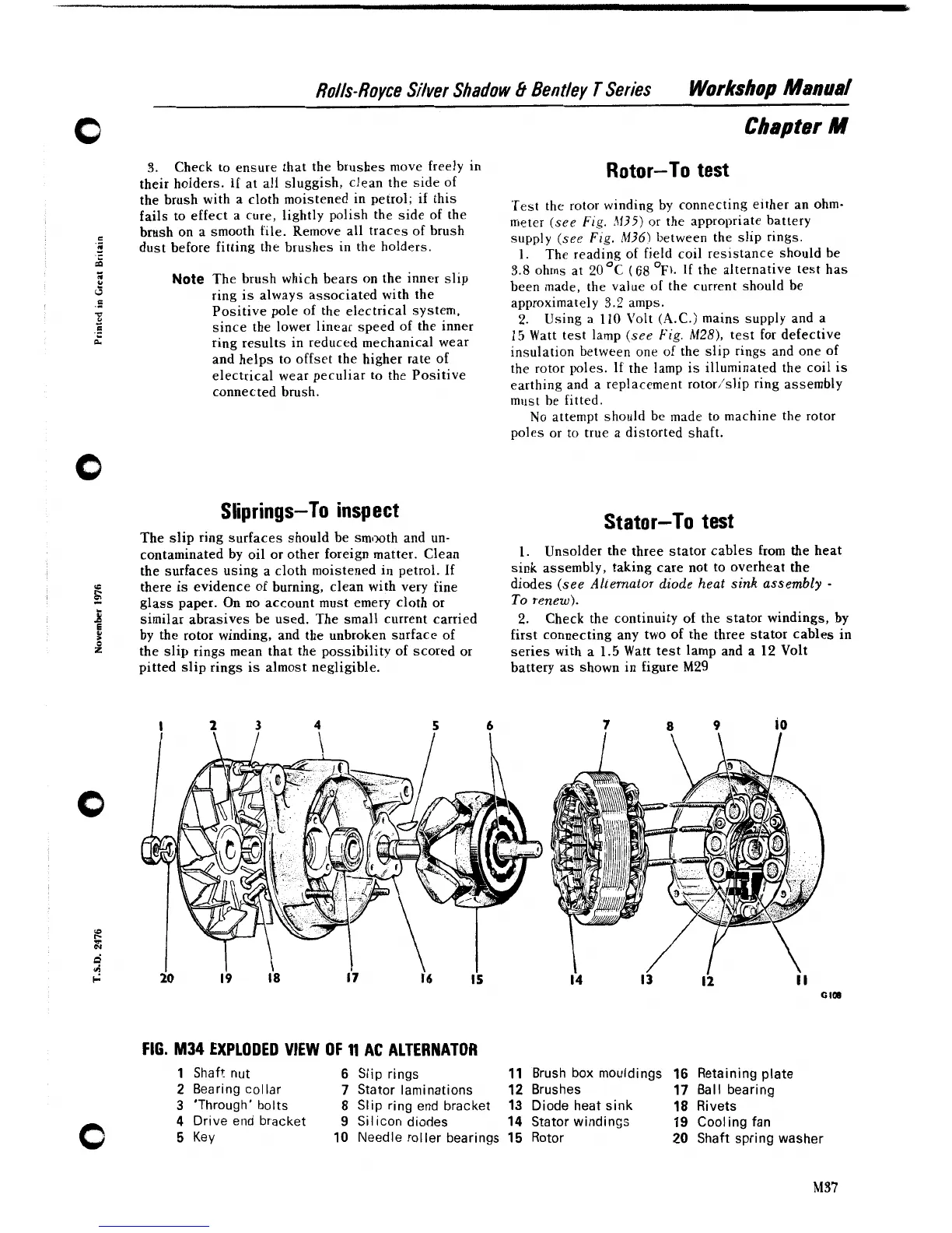
FIG.
M34
EXPLODED VIEW OF
11
AC ALTERNATOR
1
Shaft nut
6
Slip rings
11
Brush
box mouldings
16
Retaining plate
2
Bearing collar
7
Stator laminations
12
Brushes
17
Ball bearing
3
'Through' bolts
8
Slip ring end bracket
13
Diode heat sink
18
Rivets
4
Drive end bracket
9
Silicon diodes
14
Stator windings
19
Cooling fan
5
Key
10
Needle roller bearings
15
Rotor
20
Shaft spring washer