Workshop
Manual
Rolls Royce S~lver Shadow
B
Bentley
T
Ser~es
Chapter
K
FIG. K28 KICK GAP ADJUSTMENT
1
0.050
in.
(1,27
mm.) diameter drill
2
Rod holding down depression lever
3
Adjusting screw with lock-nut
Automatic Choke-To set
Automatic choke stove pipe-To check
(see
Fig.
K2q
To check the choke stove pipe for any blockages, carry
out the following operations.
1.
Disconnect the choke stove pipe at its choke
butterfly housing connection.
2. Connect the calibrated orifice
(RH
8095) to the
open end of the choke stove pipe, then connect
a
manometer capable of measuring 25 in. (63,50 cm.) of
water level difference to the orifice.
3. Run the engine until it reaches normal operating
temperature then allow the engine to idle and observe
the depression shown on the manometer. The correct
reading should be between 16 in. and 18 in.
(40,64 cm.
and
45,72
cm.).
4. If the level is less than 16 in. (40,64 cm.), examine
the pipe and choke stove assembly, remove any
blockage. After removing the blockage, again check
the manometer reading.
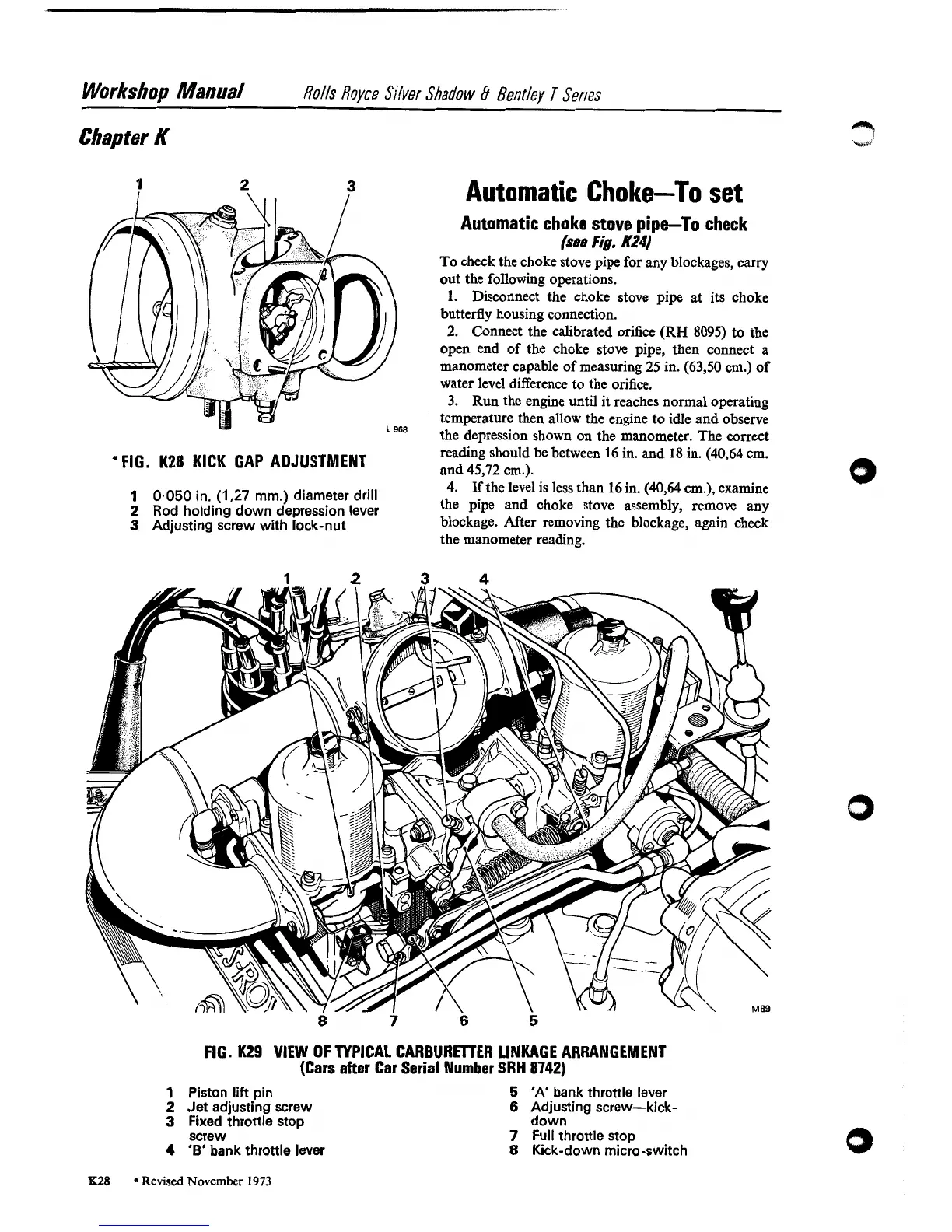
FIG.
K29
VIEW OF TYPICAL CARBUREllER LINKAGE ARRANGEMENT
(Cars after Car Serial Number SRH
8742)
1
Piston
lift
pin
2
Jet adjusting screw
3
Fixed throttle stop
screw
4
'B'
bank throttle lever
5
'A'
bank throttle lever
6
Adjusting screw-kick-
down
7
~ull
throttle stop
8
Kick-down micro-switch
K28
Revised
November
1973