Rolls-Royce Silver Shadow
&
Bentley
I
Series
Workshop
Manual
5. Remove the manometer and connect the choke
stove pipe to the choke housing.
Adjustment of kick diaphragm
1. Hold the choke butterfly closed and check the
clearance between the depression valve operating link
and the choke spindle pin. The clearance should be
0.010 in. (0,254 mm.) (see
Fig.
K27).
The clearance
can be adjusted by fitting washers on the diaphragm
operating rod.
+
Adjustment of kick-gap
(see
Fig.
K28)
The kick-gap should be set to give a reading of 0.050
in. (1,27 mm.) at the bottom of the choke valve.
To obtain this setting, proceed as follows.
1. Slacken the choke depression diaphragm locking
nut. Ensure that the choke is in the 'closed' position,
then
Dress down the depression valve operating lever,
usinga suitable rod, sdthat the depression valve link
rod bears against the end of the 2 B.A. adjusting screw.
2.
The screw should then be adjusted so that a
0.050 in.
(1,27
mm.)
diameter rod or drill can be
inserted between the butterfly housing and the butterfly
valve. Tighten the adjusting screw lock-nut
;
check the
kick-gap and adjust
if
necessary.
3.
Fit the solenoid and shims to the butterfly
housing.
Solenoid air gap
(see
Fig.
K30)
Chapter
K
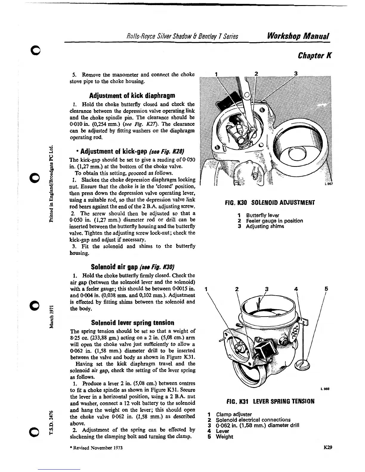
FIG.
K30 SOLENOID ADJUSTMENT
1
Butterfly lever
2
Feeler gauge in position
3
Adjusting shims
1. Hold the choke butterfly firmly closed. Check the
air gap (between the solenoid lever and the solenoid)
with
a feeler gauge; this should be between 0.0015 in.
1
and 0.004 in. (0,038 mm. and 0,102
rnm.).
Adjustment
is effected by fitting shims between the solenoid and
the body.
Solenoid lever spring tension
The spring tension should be set so that a weight of
8.25 oz. (233,88
gm.)
acting on a 2 in. (5,08 cm.) arm
will open the choke valve just sufficiently to allow a
0.062 in.
(1,58
mm.)
diameter drill to be inserted
between the valve and body as shown
in
Figure
K31.
Having set the kick diaphragm travel and the
solenoid air gap, check the setting of the lever spring
as follows.
1.
Produce a lever
2
in. (5,08 cm.) between centres
to fit a choke spindle as shown in Figure K31. Secure
-
the lever
in
a horizontal position, using a 2 B.A. nut
and washer, connect a 12 volt battery to the solenoid
FIG.
K31 LEVER SPRING TENSION
and hang the weight on the lever; this should open
the choke valve
0-062 in. (1,58 mm.) as described
Clamp adjuster
above.
2
Solenoid electrical connections
3
0.062
in.
(1,58
mm.) diameter drill
2.
Adjustment of the spring can be effected by
4
Lever
slackening the clamping bolt and turning the clamp.
5
Weight
Revised
November
1973