Workshop
Manual
Rolls Royce Silver Shadow
b
Bentley
T
Series
Chapter
J
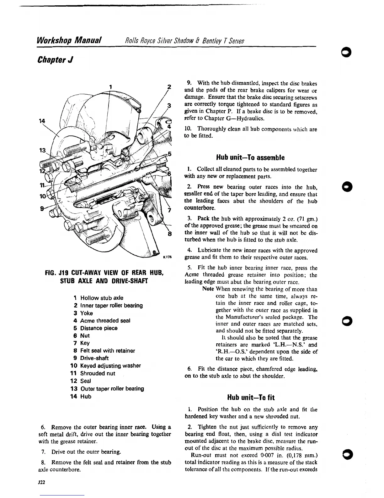
FIG.
J19
CUT-AWAY
VIEW
OF
REAR HUB,
STUB AXLE AND DRIVE-SHAFT
1
Hollow stub axle
2
Inner taper roller bearing
3
Yoke
4
Acme threaded seal
5
Distance piece
6
Nut
7
Key
8
Felt seal with retainer
9
Drive-shaft
10
Keyed adjusting washer
11
Shrouded nut
12
Seal
13
Outer taper roller bearing
14
Hub
6.
Remove the outer bearing inner race. Using
a
soft metal drift, drive out the inner bearing together
with the grease retainer.
7.
Drive out the outer bearing.
8.
Remove the felt seal and retainer from the stub
axle counterbore.
9.
With the hub dismantled, inspect the disc brakes
and the pads of the rear brake calipers for wear
or
damage. Ensure that the brake disc securing setscrews
are correctly torque tightened to standard figures as
given in Chapter P. If a brake disc is to be removed,
refer to Chapter G-Hydraulics.
10.
Thoroughly clean all hub components which are
to
be
fitted.
Hub
unit-To
assemble
1.
Collect all cleaned parts to be assembled together
with
any new or replacement parts.
2.
Press new bearing outer races into the hub,
smaller end of the taper bore leading, and ensure that
the leading faces abut the shoulders of the hub
counterbore.
3.
Pack the hub with approximately
2
oz.
(71
gm.)
of the approved grease; the grease must be smeared on
the inner wall of the hub so that it will not be dis-
turbed when the hub is fitted to the stub axle.
4.
Lubricate the new inner races with the approved
grease and fit them to their respective outer races.
5.
Fit the hub inner bearing inner race, press the
Acme threaded grease retainer into position; the
leading edge must abut the bearing outer race.
Note
When renewing the bearing of more than
one hub at the same time, always re-
tain the inner race and roller
cap, to-
gether with the outer race as supplied in
the Manufacturer's sealed package.
The
inner and outer races are matched sets.
and should not be fitted separately.
It should also
be
noted that the grease
retainers are marked
'L.H.-N.S.'
and
'R.H.-O.S.'
dependent upon the side of
the car to which they are fitted.
6.
Fit the distance piece, chamfered edge leading,
on to the stub axle to abut the shoulder.
Hub unit-To fit
1.
Position the hub on the stub axle and fit
the
hardened key washer and
a
new shrouded nut.
2.
Tighten the nut just sufficiently to remove any
bearing end float, then, using a dial test indicator
mounted adjacent to the brake disc, measure the
run-
out of the disc at the maximum possible radius.
Run-out must not exceed
0.007
in.
(0,178
mm.)
total indicator reading as this is a measure of the stack
tolerance of all the components. If the run-out exceeds