Rolls-Royce Silver
Shadow
B
Bentley
T
Series
Workshop
Manus/
special hydraulic ram
(RH
8017) and special extrac-
tor beam (RH 8033).
3. Remove the pinion oil seal and the oil
flinger
fitted behind it.
4.
Place the housing in a press
with
the
pinion
gear downward and the housing lower end
firmly
supported and carefully press the pinion out of the
housing.
5.
Collect the adjusting washers from the pinion
shank and the taper roller bearing from the housing.
6.
If new taper roller bearings are to be fitted, the
outer tracks must be removed from the housing,
using a soft drift and a hammer, taking
care
to avoid
damage to the bearing locating bores.
7.
The large roller bearing should be removed from
beneath the pinion head using a press and the special
tool
(RH
7863).
8.
Wash all parts thoroughly in paraffin and
dry
with compressed air.
9. Inspect all parts for
serviceability, and any
showing damage, pitting or excessive wear should
be
renewed.
Pinion housing--To
assemble
Prepare the washed and inspected parts, complete
with any new or replacement parts for assembly,
as
follows.
1. Lightly lubricate all components paying parti-
cular attention to the roller bearing races.
2.
If
new bearings are being fitted, carefully press
the outer tracks into the housing and the large roller
bearing on to the pinion, ensuring that the bearings
are square and right up to their abutment faces.
3.
Enter the pinion into the housing then fit the
two adjusting washers on to the pinion shank (see
Fig.
56).
Note On cars produced from
car
numbers
SRH 4231-Standard cars, CRH
5003-
Coachbuilt cars and 5RX 6159-cars
built to meet the American Federal
Safety Standard Requirements, a spacer
is fitted to the final drive pinion between
the large roller bearing and the adjusting
washers
(see
Fig.
56).
The two washers determine the pre-load on the
pinion bearing and it is important that the washers
are
free from defects and are
flat
and
parallel
to within
0.001 in. (0,025
mm.).
If
the pinion assembly bearings have not been
renewed, the original washers may be used.
If
new
Chapter
J
bearings
have
been
fitted, experience
has
shown that
washers whose combined thickness amounts to bet-
ween
0-270 in. and 0.280 in. (6,85
mm.
and 8,89
mm.)
should
give
the best initial setting.
4.
Support the pinion and housing and pms the
upper bearing on to the pinion shank until it abuts
the adjusting washers.
5.
Fit
the
oil flinger and a new
seal
to
the
housing
with
the
Front fact of the seal just flush with the fact
of the housing
and
the seal lip pointing inward.
6.
Fit the transmission damper to the pinion
flange
md
enter
the
huge into the housing, taking
care
not
to
damage
the
seal,
and fit the lock washer and nut.
7. Tighten the nut to a torque figure of between
275 lb.
R.
and 300 lb.
ft.
(38 kg.m. and
41,46
kg.m.)
locking the pinion
flange
using the special tool
(RH
7862). Do not turn over the tab of the lock-
washer.
8.
Rotate the pinion several
times
in both directions
then
check
the
pre-load
Thc
pload on the pinion
bearings
when the
housing
is
out of
the
final
drive casing should
be
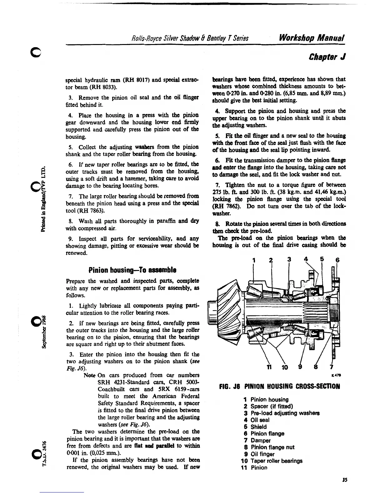
FIG.
56
PINION HOUSING CROSS-SECTION
1
Pinion housing
2
Spacer (if fitted)
3
Pre-load adjusting washers
4
Oil seal
5
Shield
6
Pinion flange
7
Damper
8
Pinion flange nut
9
Oil finger
10
Taper roller bearings
11
Pinion