Workshop
Manual
Rolls Rovce Silver
Shadow
8
Bentlev
T
Series
Chapter
J
15. Fit the two adjusting washers behind the crown
wheel bearing and fit the left-hand side housing.
Progressively tighten the housing nuts whilst rocking
the crown wheel back and forth to ensure that there
is still backlash between the gears.
16. Mount a dial test indicator on the final drive
casing with the indicator pad on the flank of a crown
wheel tooth.
17. Zero the indicator and rock the crown wheel
back and forth noting the backlash.
18. The backlash should be checked at twelve posi-
tions around the crown wheel and an average reading
taken. This figure should conform to the backlash
figure etched on the crown wheel.
19. If it does not conform, the thickness of the
washers behind the crown wheel bearing must be
varied to obtain the correct reading.
These washers are available in a range from
0.1 11
in.
to 0.129 in. (2,819 mm. to 3,27
mm.)
in
increments
of
0.002 in. (0,050 mm.) and it can be assumed that
0.001 in. (0,025
mm.)
variation in the thickness of the
,,,,
adjusting washer
will
make a difference of 0.001 in.
(0,025
mm.)
to the backlash.
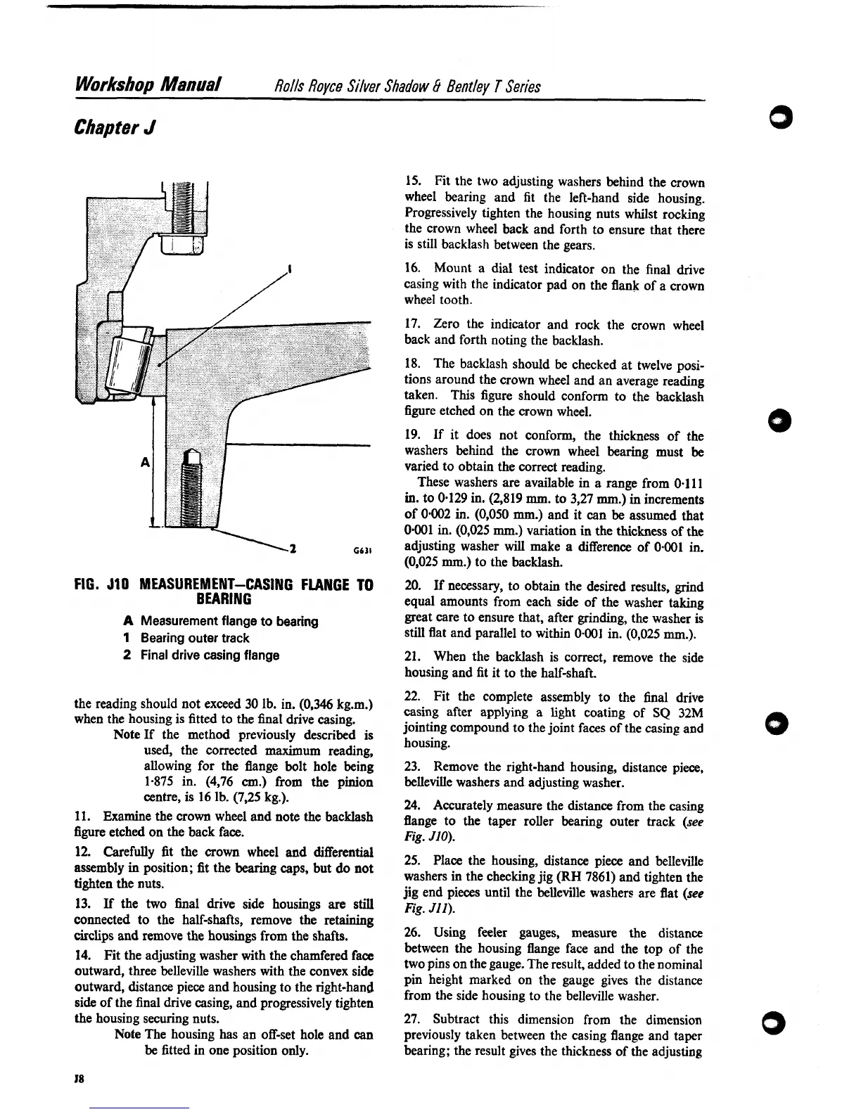
FIG.
J10
MEASUREMENT-CASING FLANGE
TO
20.
If
necessary, to obtain the desired results, grind
BEARING
equal amounts from each side of the washer taking
A
Measurement flange to bearing
great care to ensure that, after grinding, the washer is
1
Bearing outer track
still flat and parallel to within
0.001 in. (0,025
mm.).
2
Final drive casing flange 21. When the backlash is correct, remove the side
housing and fit it to the half-shaft.
22. Fit the complete assembly to the final drive
the reading should not exceed 30 lb. in. (0,346 kg.m.1
Easing
after
applying
a
Bght
coating
of
SQ
32M
when the housing
is
fitted to the final drive casing.
jointing compound to the joint faces of the casing and
Note
If
the method previously described is
used, the corrected maximum reading,
allowing for the flange bolt hole
being
23. Remove the right-hand housing, distance piece,
1.875 in. (4,76
cm.)
from the pinion belleville washers and adjusting washer.
centre, is
16
lb. (7,25 kg.).
24.
Accurately measure the distance from the casing
11. Examine the crown wheel and note the backlash
flange to the taper roller bearing outer track (see
figure etched on the back face.
Fig.
JIO).
-
l2
fit
the
crown
and
25. Place the housing, distance piece and belleville
assembly
in
position; fit the bearing caps, but do not
tighten the nuts.
washers in the checking jig
(RH
7861) and tighten the
jig end pieces until the belleville washers are flat (see
13.
If
the two final drive side housings are still
fi.
~11).
connected to the half-shafts, remove the retaining
circlips and remove the housings from the shafts. 26. Using feeler gauges, measure the distance
between the housing flange face and the top of the
14.
Fit the adjusting washer with the chamfered face
two
pins
on
the
gauge.
The
result,
added
to
the
outward, three belleville washers with the convex side
pin
height
on
the
gauge
gives
the
distance
outward, distance piece and housing to the right-hand
side of the final drive casing, and progressively tighten
from the side housing to the belleville washer.
the housing securing nuts. 27. Subtract this dimension from the dimension
Note The housing has an off-set hole and
can
previously taken between the casing flange and taper
be fitted in one position only. bearing; the result gives the thickness of the adjusting