Rolls-Royce Silver Shadow
t9
Bentley
T
Series
Workshop
Manuid
Chapter
K
Section
K4
THE CARBURETTERS AND AUTOMATIC
CHOKE SYSTEM
Carburetters-To remove
(see Chapter
E-
En#ine Compartment illustrations)
1.
Disconnect the battery leads.
2.
If a hot idle compensator valve is fitted disconnect
the rubber pipe connected to the choke butterfly hous-
ing rubber elbow; also remove the rubber pipe
connected
td the carburetter 'Tee' piece.
3.
Remove the air hose steady bracket noting that
the small bracket retaining the kick-down micro-
switch wire is retained by one screw.
4.
Disconnect the hose from the air silencer and
butterfly housing; remove the hose together with the
bonding cable earth strip (if
fitt~d).
5.
Move the spring clip away from the choke
solenoid cover then disconnect the wires noting from
which terminal each wire was removed to ensure
correct assembly.
For engines fitted with a refrigeration fast-idle solenoid
carry
out Operations
6
and
7.
6.
Disconnect the two rubber tubes connected to
the refrigeration fast-idle solenoid noting their respec-
tive connections for correct assembly.
7.
Disconnect the wiring to the refrigeration fast-
idle solenoid noting the colour of the wiring to avoid
incorrect assembly.
8.
Remove the engine oil dipstick.
9.
Remove the split pin, washers and swivel pin,
securing the throttle linkage to the fore and after
manifold shaft lever; this connection is adjacent to the
'A'
bank carburetter.
10.
Disconnect the distributor vacuum pipe (if fitted).
11.
Disconnect the main fuel feed pipe.
12.
Disconnect the fuel spill pipe.
13.
Disconnect the choke stove pipe from the choke
housing.
14.
Remove the three small screws securing the small
end cover to the bi-metal coil cover then withdraw
the cover along the choke stove pipe to reveal the pipe
connection. Disconnect the choke stove pipe.
15.
Remove the crankcase breather pipe from the
choke butterfly housing; withdraw the housing from
the end of the pipe.
16.
Cars from Car Serial Number
SRH
8742
and
onwards. Disconnect
thz hose from the carburetter
weakening device and discard the retaining clip.
17.
Remove the wires connected to the micro-
switch(es) adjacent to the carburetters noting their
respective position to avoid incorrect assembly.
18.
Remove the air horns, the choke butterfly hous-
ing, the carburetters and the 'Tee' piece as a complete
assembly. This assembly is secured to the induction
manifold by a setscrew, location being provided by
two dowel pins.
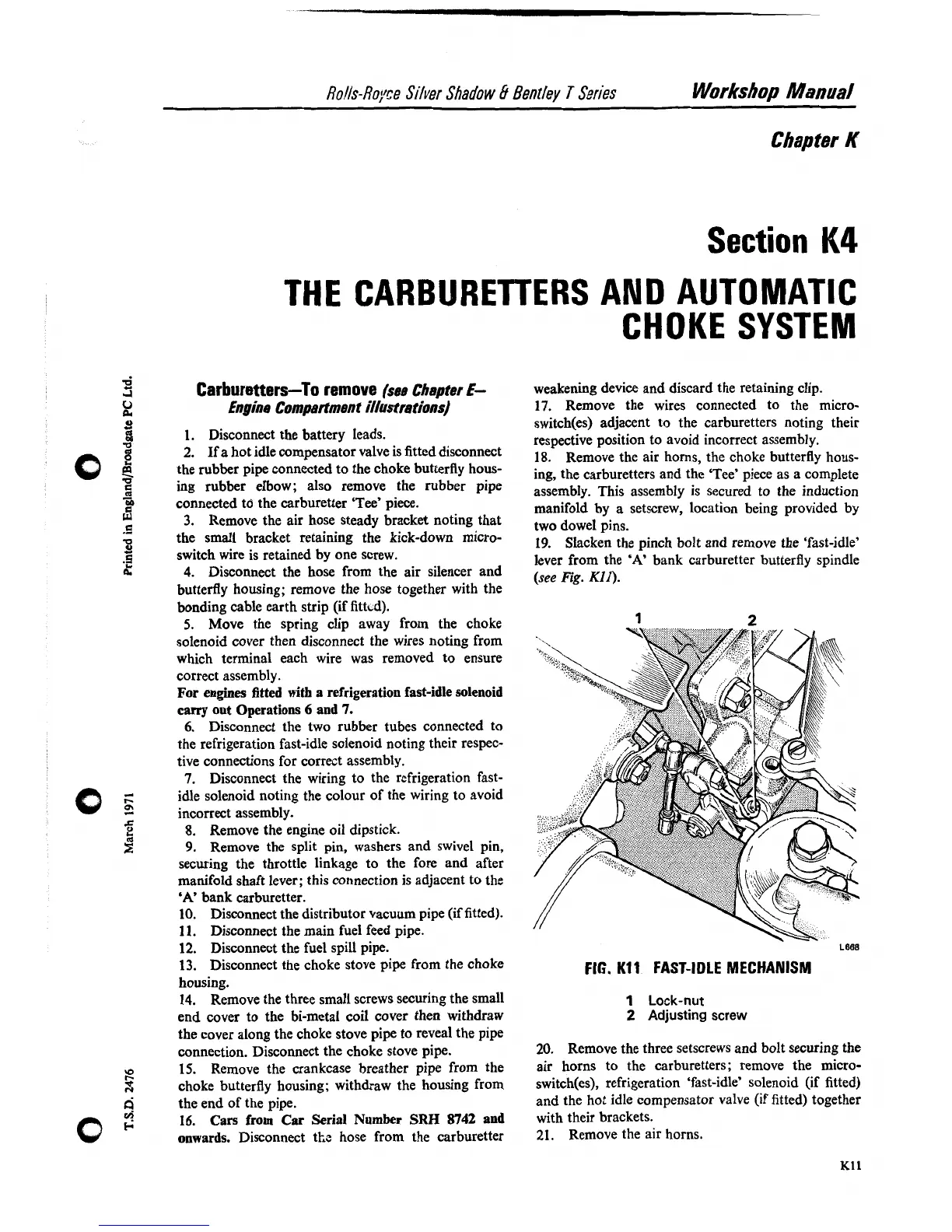
19.
Slacken the pinch bolt and remove the 'fast-idle'
lever from the
'A'
bank carburetter butterfly spindle
(see
Fig.
KII).
LESS
FIG.
Kl1
FAST-IDLE MECHANISM
1
Lock-nut
2
Adjusting screw
20.
Remove the three setscrews and bolt securing the
air horns to the carburetters; remove the micro-
switch(es), refrigeration 'fast-idle' solenoid (if fitted)
and the hot idle compensator valve (if fitted) together
with their brackets.
21.
Remove the air horns.