Rolls-tiojce Silver Shadow
6
Bentley
T
Series
Workshop
Manual
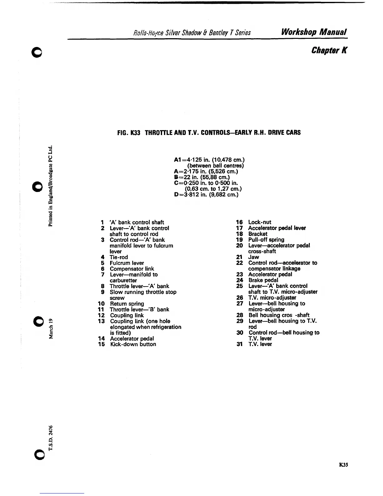
FIG.
K33
THROllLE AND T.V. CONTROLS-EARLY R.H. DRIVE CARS
1
'A'
bank control shaft
2
Lever-'A' bank control
shaft to control rod
3
Control rod-'A' bank
manifold lever to fulcrum
lever
4
Tie-rod
5
Fulcrum lever
6
Compensator link
7
Lever-manifold to
carburetter
8
Throttle lever-'A' bank
9
Slow running throttle stop
screw
10
Return spring
11
Throttle lever-'B' bank
12
Coupling link
13
Coupling link (one hole
elongated when refrigeration
is fitted)
14
Accelerator pedal
15
Kick-down button
A1 =4.125 in. (1 0,478 cm.)
(between ball centres)
A=2.175 in. (5,526 cm.)
B=22 in. (55,88 cm.)
C=0.250 in. to 0.500 in.
(0,63 cm. to 1,27 cm.)
D=3.812 in. (9,682 cm.)
Chapter
K
Lock-nut
Accelerator pedal lever
Bracket
Pull-off spring
Lever-accelerator pedal
cross-shaft
Jaw
Control rod-accelerator to
compensator linkage
Accelerator pedal
Brake pedal
Lever-'A' bank control
shaft to T.V. micro-adjuster
T.V. micro-adjuster
Lever-bell housing to
micro-adjuster
Bell housing cros -shaft
Lever-bell housing to T.V.
rod
Control rod-bell housing to
T.V. lever
T.V. lever