Workshop
Manual
Rolls- Royce Silver Shadow
B
Bentley
T
Series
Chapter
M
6.
Start the engine and run the genelator at
1500
r.p.m.
7.
Using
'
Lucas' tool (543-817-42), turn the
voltage adjustment cam until the correct setting is
obtained (turning the tool clockwise raises the
setting and turning the tool anti-clockwise lowers
the setting).
8.
Stop and then re-start the engine and repeat the
test to check the regulator settings.
9.
Fit the original connections and fit the control
box cover.
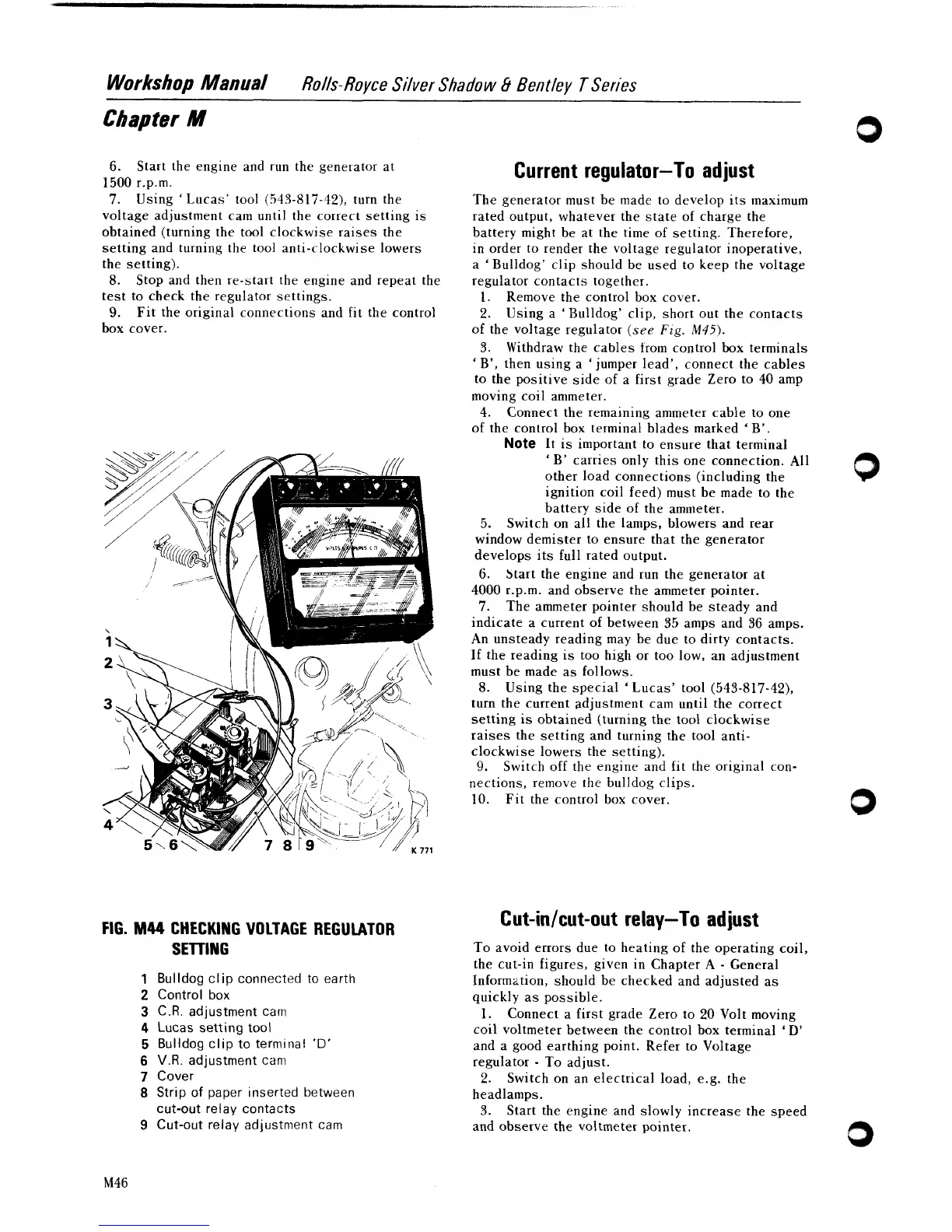
FIG.
M44
CHECKING VOLTAGE REGULATOR
SETTING
1
Bulldog clip connected to earth
2
Control box
3
C.R. adjustment cam
4
Lucas setting tool
5
Bulldog clip to terminal
'D'
6
V.R.
adjustment can1
7
Cover
8
Strip of paper inserted between
cut-out relay contacts
9
Cut-out relay adjustment cam
Current regulator-To
ad
just
The generator must be made to develop its maximum
rated output, whatever the state of charge the
battery might be at the time of setting. Therefore,
in order to render the voltage regulator inoperative,
a
'
Bulldog' clip should be used to keep the voltage
regulator contacts together.
1.
Remove the control box cover.
2.
Using a 'Bulldog' clip, short out the contacts
of the voltage regulator
(see
Fig.
M45).
3. Withdraw the cables trom control box terminals
'
B', then using a 'jumper lead', connect the cables
to the positive side of a first grade Zero to 40 amp
moving coil ammeter.
4.
Connect the remaining ammeter cable to one
of the control box terminal blades marked
'
B'.
Note
It
is important to ensure that terminal
'
B' carries only this one connection. All
other load connections (including the
ignition coil feed) must be made to the
battery side of the ammeter.
5.
Switch on all the lamps, blowers and rear
window demister to ensure that the generator
develops its full rated output.
6.
Start the engine and run the generator at
4000
r.p.m. and observe the ammeter pointer.
7.
The ammeter pointer should be steady and
indicate a current of between 35 amps and 36 amps.
An unsteady reading may be due to dirty contacts.
If
the reading is too high or too low, an adjustment
must be made as follows.
8.
Using the special 'Lucas' tool (543-817-42),
turn the current adjustment cam until the correct
setting is obtained (turning the tool clockwise
raises the setting and turning the tool
anti-
clockwise lowers the setting).
9.
Switch off the engine and fit the original con-
nections, remove the bulldog clips.
10.
Fit the control box cover.
Cut-inlcut-out relay-To adjust
To avoid errors due to heating of the operating coil,
the cut-in figures, given in Chapter
A
-
General
Inform~tion, should be checked and adjusted as
quickly as possible.
1. Connect a first grade Zero to 20 Volt moving
coil voltmeter between the control box terminal
'
D'
and a good earthing point. Refer to Voltage
regulator
-
To adjust.
2.
Switch on an electrical load,
e.g. the
headlamps.
3.
Start the engine and slowly increase the speed
and observe the voltmeter pointer.