Workshop
Manual
Rolls- Royce Silver Shadow
8
Bentley
T
Series
Chapter
Q
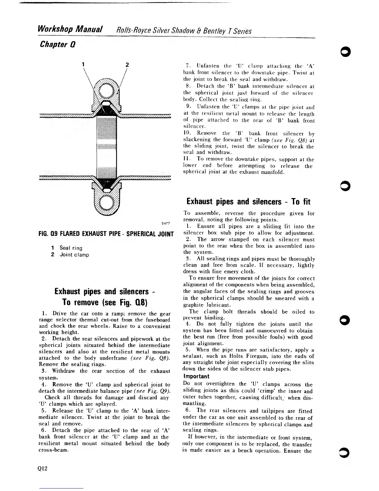
FIG.
09
FLARED EXHAUST PIPE
-
SPHERICAL JOINT
1
Seal
ring
2
Joint
clamp
Exhaust pipes and silencers
-
To remove (see
Fig.
Q8)
1.
Drive the car onto a ramp; remove the gear
range selector thermal cut-out from the fuseboard
and chock the rear wheels. Raise to a convenient
working height.
2.
Detach the rear silencers and pipework at the
spherical joints situated behind the intermediate
silencers and also at the resilient metal mounts
attached to the body underframe
(see
Fig.
48).
Remove the sealing rings.
3.
Withdraw the rear section of the exhaust
system.
4.
Remove the
'U'
clamp and spherical joint to
detach the intermediate balance pipe
(see
Fig.
49).
Check all threads for damage and discard any
'U'
clamps which are splayed.
5.
Release the
'U'
clamp to the
'A'
bank inter-
mediate silencer. Twist at the joint to break the
seal and remove.
6.
Detach the pipe attached to the rear of
'A'
bank front silencer at the
'U'
clamp and at the
resilient metal mount situated behind the body
cross-beam.
7.
llnfasten the
'IJ'
clamp attaching the 'A'
bank front silencer to the
downtake pipe. Twist at
the joint to break the seal and withdraw.
8.
Detach the
'B'
bank intermediate silencer at
the spherical joint
just
forward of the silencer
body. Collect the sealing ring.
9.
Unfasten the 'li' clamps at the pipe joint and
at the
rrsilic~lt metal mount to release the length
of pipe attached to the rear of
'B'
bank front
silencer.
10. Remove the
'B'
bank front silencer by
slackening the forward
'U'
clamp
(see
Fig.
48)
at
the sliding joint, twist the silencer to break the
seal and withdraw.
11. To remove the
downtake pipes, support at the
lower end before attempting to release the
spherical joint at the exhaust manifold.
Exhaust pipes and silencers
-
To fit
To assemble, reverse the procedure given for
removal, noting the following points.
1.
Ensure all pipes are a sliding fit into the
silencer
box stub pipe to allow for adjustment.
2.
The arrow stamped on each silencer must
point to the rear when the box is assembled into
the system.
3.
All sealing rings and pipes must be thoroughly
clean and free from scale. If necessary, lightly
dress with fine emery cloth.
To ensure free movement of the joints for correct
alignment of the components when being assembled,
the angular faces of the sealing rings and grooves
in the spherical clamps should be smeared with a
graphite lubricant.
The clamp bolt threads should be oiled to
prevent binding.
4.
Do not fully tighten the joints until the
system has been fitted and manoeuvred to obtain
the best run (free from possible fouls) with good
joint alignment.
5.
When the pipe runs are satisfactory, apply a
sealant, such as Holts
Firegum, into the ends of
any straight tube joint especially covering the slits
down the sides of the silencer stub pipes.
Important
Do not overtighten the
'U'
clamps across the
sliding joints as this could 'crimp' the inner and
outer tubes together, causing
difficu!t; when dis-
mantling.
6.
The rear silencers and tailpipes are fitted
under the car as one unit assembled to the rear of
the intermediate silencers by spherical clamps and
sealing rings.
If
however, in the intermediate or front system,
only one component is to be replaced, the transfer
is made easier as a bench operation. Ensure the