Workshop
Manual
Rolls Royce Silver Shadow
d
Bentley
T
Series
Chapter
K
C
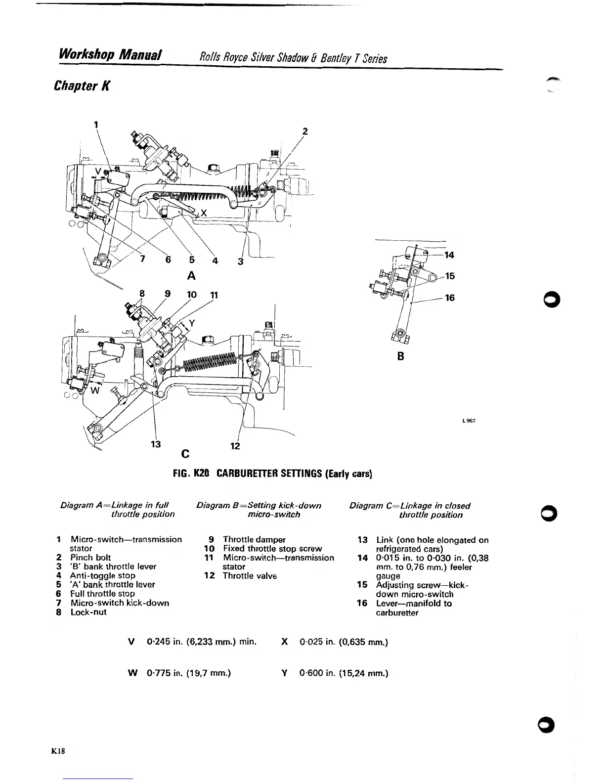
FIG.
K20
CARBUREllER SElllNGS
(Early cars)
Diagram
A
=Linkage in full
Diagram
B
=Setting kick- down
Diagram
C=Linkage in closed
throttle position micro-switch throttle position
Micro-switch-transmission
9
stator
10
Pinch bolt
11
'B'
bank throttle lever
Anti-toggle stop
12
'A'
bank throttle lever
Full throttle stop
Micro-switch kick-down
Lock-nut
Throttle damper
13
Link (one hole elongated on
Fixed throttle stop screw refrigerated cars)
Micro-switch-transmission
14
0.01
5
in. to 0-030 in. (0,38
stator
mrn. to 0,76 mm.) feeler
Throttle valve
gauge
15
Adjusting screw-kick-
down micro-switch
16
Lever-manifold
to
carburetter
V
0.245 in. (6,233 mm.) min.
X
0.025 in. (0,635 mm.)
W
0.775 in. (1 9.7 mm.)
Y
0.600 in. (1 5.24 mm.)