Rolls-Royce Silver Shadow
8
Bentley
T
Series
Workshop
Manual
7.
Remove the three through bolts and spring
washers and withdraw the DE shield complete with
rotor. If 'Loctite' grade A has been used to secure
the through bolts, local heat should be applied with
a heated soldering iron to loosen them, the part
should not be overheated. If necessary use a hide
faced hammer and gently tap the DE shield away
from the stator and SRE shield. Do not damage the
slip ring when laying the DE shield and rotor
assembly on the bench.
Note
The stator is sandwiched between the
two end-shields therefore great care must
be taken at this stage to prevent the full
weight of the stator from falling onto the
three stator phase leads.
8.
Lay the stator and SRE shield assembly
carefully on the bench with the endshield uppermost.
9.
Unsolder the three stator phase leads from the
heatsink terminal tags (do not remove tags from
heatsinks) and separate the SRE shield from the
stator using a hide faced mallet if necessary.
10.
Remove and discard the
'0'
ring from the
shield bearing housing using a sharp pointed probe.
Do not damage the
'0'
ring groove.
11.
Place the DE shield with drive shaft upwards
over a suitable large diameter cylinder so that the
Chapter
M
rotor is encased within the cylinder arid the cylinder
sits squarely against the three end shield webs.
Support the rotor from underneath and gently press
the rotor from the DE shield with a standard
fly-
press.
Note It is unnecessary to strip the diode
assembly from the SRE shield unless it
is established that there is a fault in
one or more of the diodes. Accordingly,
the diodes should next be subjected to
the tests detailed under Alternator
-
Bench testing. If a faulty diode is
detected proceed as instructed in
Alternator
-
Inspection and repair.
Alternator-Inspection and repair
General
After dismantling, all components which require
cleaning should be thoroughly cleaned.
1.
Examine all parts for cracking, corrosion,
serviceability of threads, score marks and excessive
wear. The 'nyloc' pulley nut may be used again
provided that the nylon insert is in reasonable
condition.
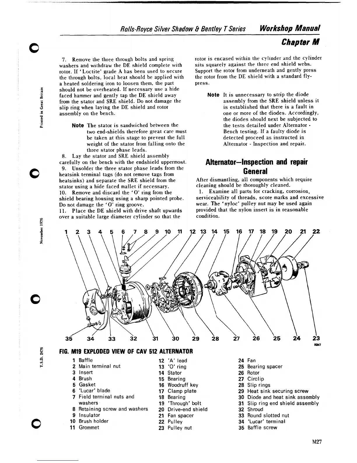
FIG.
MI9
EXPLODED VIEW OF CAV
512
ALTERNATOR
1
Baffle
12
'A'
lead
2
Main terminal nut
13
'0'
ring
3
Insert
14
Stator
4
Brush
15
Bearing
5
Gasket
16
Woodruff key
6
'Lucar' blade
17
Clamp plate
7
Field terminal nuts and
18
Bearing
washers
19
'Through' bolt
8
Retainingscrewandwashers
20
Drive-endshield
9
Insulator
21
Fan spacer
10
Brush holder
22
Pulley
11
Grommet
23
Pulley nut
24
Fan
25
Bearing spacer
26
Rotor
27
Circlip
28
Slip rings
29
Heat sink securing screw
30
Diode and heat sink assembly
31
Slip ring end shield assembly
32
Shroud
33
Round slotted nut
34
'Lucar' terminal
35
Baffle screw