Workshop
Manual
Rolls-Royce Silver Shadow
8
Bentley
T
Series
Chapter
M
a. Switch the ignition on and observe that the
warning lamp
n~arked CEN illuminates.
b. Switch on all the electrical loads with the
exception of the windscreen wipers.
c. Start the engine, allow it to run at approx-
imately 1000 r.p.m. and observe that the
warning lamp is extinguished.
d. Momentarily increase the engine speed to
approximately 3000
r.p.m. and observe that
the alternator current is approximately 53
amps.
e. With the engine running at approximately
1500
r.p.m. switch off all the loads. The
voltage should rise to between 14.0 and
14.5
volts and then remain constant, the
current reading should drop appreciably.
4.
Should there be a fault in the system this will
be apparent by one or more of the following
symptoms:
a. If the warning lamp does not illuminate
check the bulb and renew if defective.
b. If the bulb is serviceable but does not
illuminate, check the regulator by first
switching off the engine and disconnecting
the lead from terminal
F
on the regulator.
Clip this lead to earth and switch on the
engine. If the lamp now illuminates the
regulator is faulty and must be replaced by
a new regulator.
If
the lamp still remains
unlit then the alternator is faulty and
requires workshop attention (see
Alternator
-
To dismantle).
The tests described in 5 may be used to
locate the alternator fault. Having located
the fault, switch off the engine and
reconnect the
F
lead to
F
terminal.
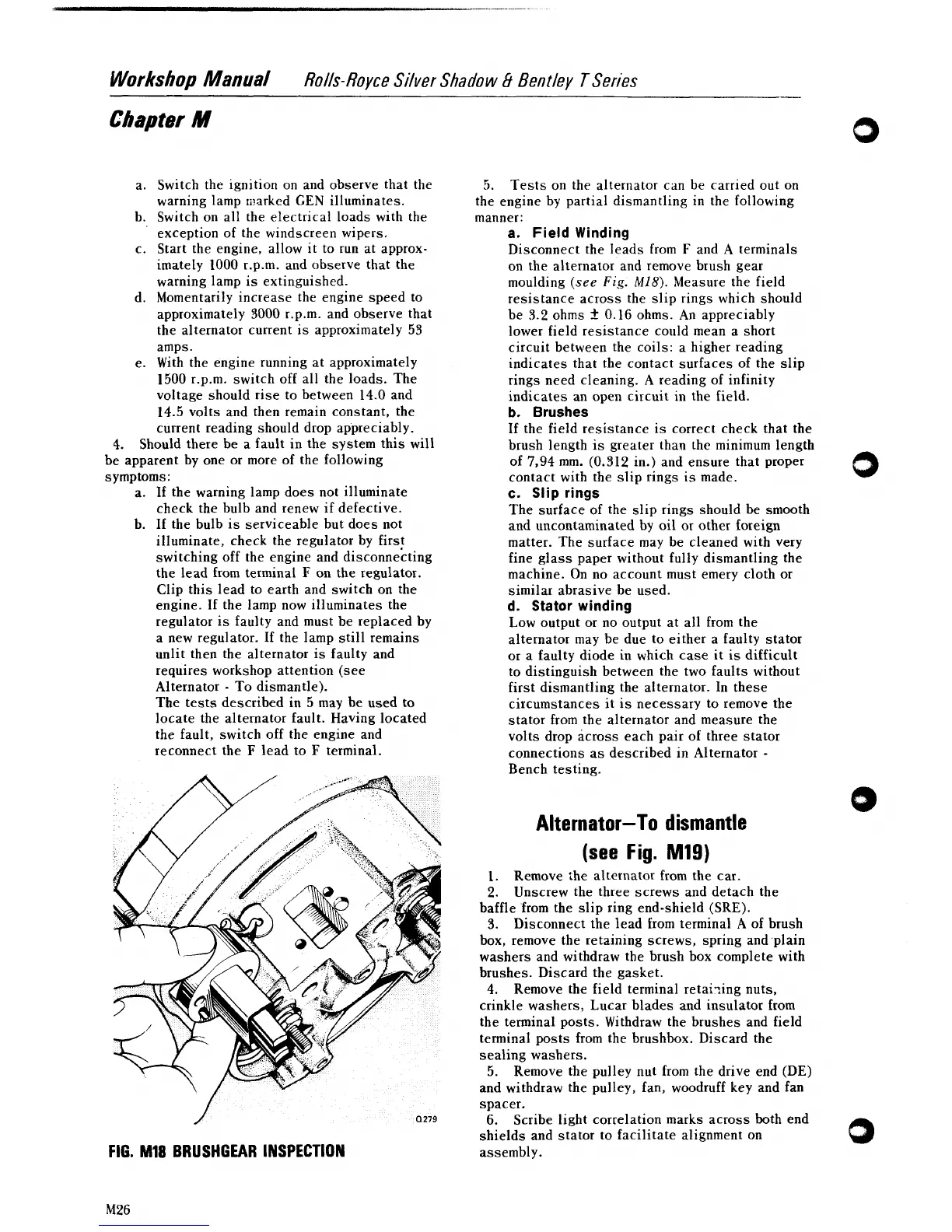
FIG.
MI8
BRUSHGEAR INSPECTION
5.
Tests on the alternator can be carried out on
the engine by partial dismantling in the following
manner:
a.
Field Winding
Disconnect the leads from
F
and
A
terminals
on the alternator and remove brush gear
moulding
(see
Fig.
M18).
Measure the field
resistance across the slip rings which should
be
3.2
ohms
2
0.16 ohms. An appreciably
lower field resistance could mean a short
circuit between the coils: a higher reading
indicates that the contact surfaces of the slip
rings need cleaning. A reading of infinity
indicates an open circuit in the field.
b.
Brushes
If the field resistance is correct check that the
brush length is greater than the minimum length
of
7,94
mm. (0.312 in.) and ensure that proper
contact with the slip rings is made.
c.
Slip rings
The surface of the slip rings should be smooth
and uncontaminated by oil or other foreign
matter. The surface may be cleaned with very
fine glass paper without fully dismantling the
machine. On no account must
emery cloth or
similar abrasive be used.
d.
Stator winding
Low output or no output at all from the
alternator may be due to either a faulty stator
or a
faulty diode in which case it is difficult
to distinguish between the two faults without
first dismantling the alternator. In these
circumstances it is necessary to remove the
stator from the alternator and measure the
volts drop across each pair of three stator
connections as described in Alternator
-
Bench testing.
Alternator-To dismantle
(see
Fig.
M19)
1.
Remove ihe alternator from the car.
2.
Unscrew the three screws and detach the
baffle from the slip ring end-shield (SRE).
3..
Disconnect the lead from terminal
A
of brush
box, remove the retaining screws, spring and plain
washers and withdraw the brush box complete with
brushes. Discard the gasket.
4.
Remove the field terminal retaiying nuts,
crinkle washers, Lucar blades and insulator from
the terminal posts. Withdraw the brushes and field
terminal posts from the brushbox. Discard the
sealing washers.
5.
Remove the pulley nut from the drive end (DE)
and withdraw the pulley, fan, woodruff key and fan
spacer.
6.
Scribe light correlation marks across both end
shields and stator to facilitate alignment on
assembly.
0