Worksho~
Manual
Rolls
Royce
Silver
Shadow
8
Bentley
T
Series
Chapter
K
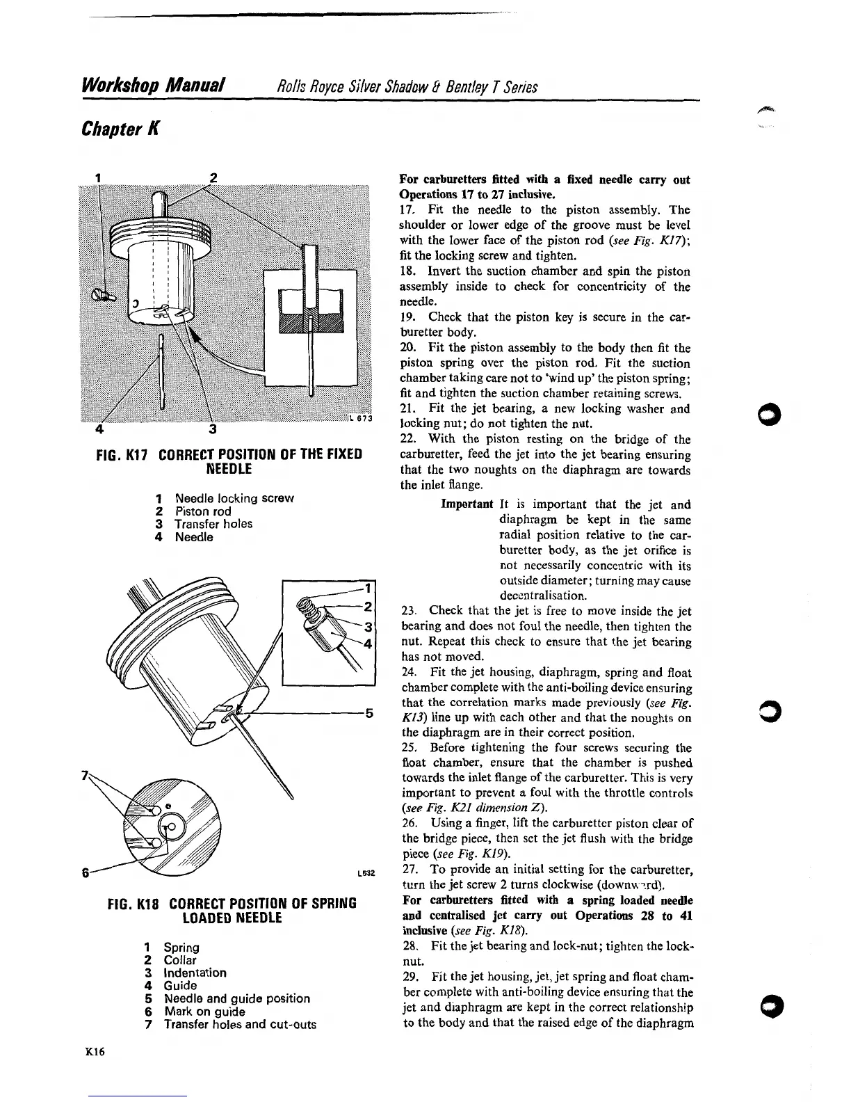
FIG.
K17
CORRECT POSITION OF THE FIXED
NEEDLE
1
Needle locking screw
2
Piston rod
3
Transfer holes
4
Needle
FIG.
K18
CORRECT POSITION OF SPRING
LOADED NEEDLE
1
Spring
2
Collar
3
Indentation
4
Guide
5
Needle and guide position
6
Mark
on guide
7
Transfer holes and cut-outs
For carburetters fitted with a fixed needle carry out
Operations
17
to
27
inclusive.
17.
Fit the needle to the piston assembly. The
shoulder or lower edge of the groove must be level
with the lower face of the piston rod
(see Fig.
K17);
fit the locking screw and tighten.
18.
Invert the suction chamber and spin the piston
assembly inside to check for concentricity of the
needle.
19. Check that the piston key is secure in the car-
buretter body.
20. Fit the piston assembly to the body then fit the
piston spring over the piston rod. Fit the suction
chamber taking care not to 'wind up' the piston spring;
fit and tighten the suction chamber retaining screws.
21. Fit the jet bearing, a new locking washer and
locking nut; do not tighten the nut.
22. With the piston resting on the bridge of the
carburetter, feed the jet into the jet bearing ensuring
that the two noughts on the diaphragm are towards
the inlet flange.
Important
It is important that the jet and
diaphragm be kept in the same
radial position relative to the car-
buretter body, as the jet orifice is
not necessarily concentric with its
outside diameter; turning may cause
decentralisation.
23. Check that the jet is free to move inside the jet
bearing and does not foul the needle, then tighten the
nut. Repeat this check to ensure that the jet bearing
has not moved.
24. Fit the jet housing, diaphragm, spring and float
chamber complete with the anti-boiling device ensuring
that the correlation marks made previously
(see Fig.
K13) line up with each other and that the noughts on
the diaphragm are in their correct position.
25.
Before tightening the four screws securing the
float chamber, ensure that the chamber is pushed
towards the inlet flange of the carburetter. This is very
important to prevent a foul with the throttle controls
(see Fig.
K21
dimension
2).
26.
Using a finger, lift the carburetter piston clear of
the bridge piece, then
sct the jet flush with the bridge
piece
(see
Fig.
K19).
27.
To provide an initial setting for the carburetter,
turn the jet screw
2
turns clockwise (downw7.rd).
For carburetters fitted with
a
spring loaded needle
and centralised jet carry out Operations
28
to
41
inclusive
(see
Fig.
K18).
28.
Fit the jet bearing and lock-nut; tighten the lock-
nut.
29. Fit the jet housing, jet, jet spring and float cham-
ber
con~plete with anti-boiling device ensuring that the
jet and diaphragm are kept in the correct relationship
to the body and that the raised edge of the diaphragm