Workshop Manual
Rolls Royce S~lver Shadow
B
Bentley
T
Series
Chapter
K
tion is to draw
air
through the carbon, extracting the
in order to extract the polyurethane foam filter
fuel vapour as it does so for consumption in the engine.
element.
A
detachable cover is situated in the left-
The upper section of the canister is open to the atmos- hand valance, adjacent to the blower motor resistances
phere and houses a polyurethane foam filter to ensure
(see
Fig.
K40).
that the air drawn through the carbon is clean.
1.
Unscrew the four screws retaining the access
cover, lift off the cover and withdraw the filter element
Polyurethane foam filter element-
from the top of the canister.
To renew
When fitting a new filter element, ensure that it is
correctly positioned inside the retaining rim of the
-
It is not necessary to remove the canister from the car canister. Fit the access cover and tighten the setscrews.
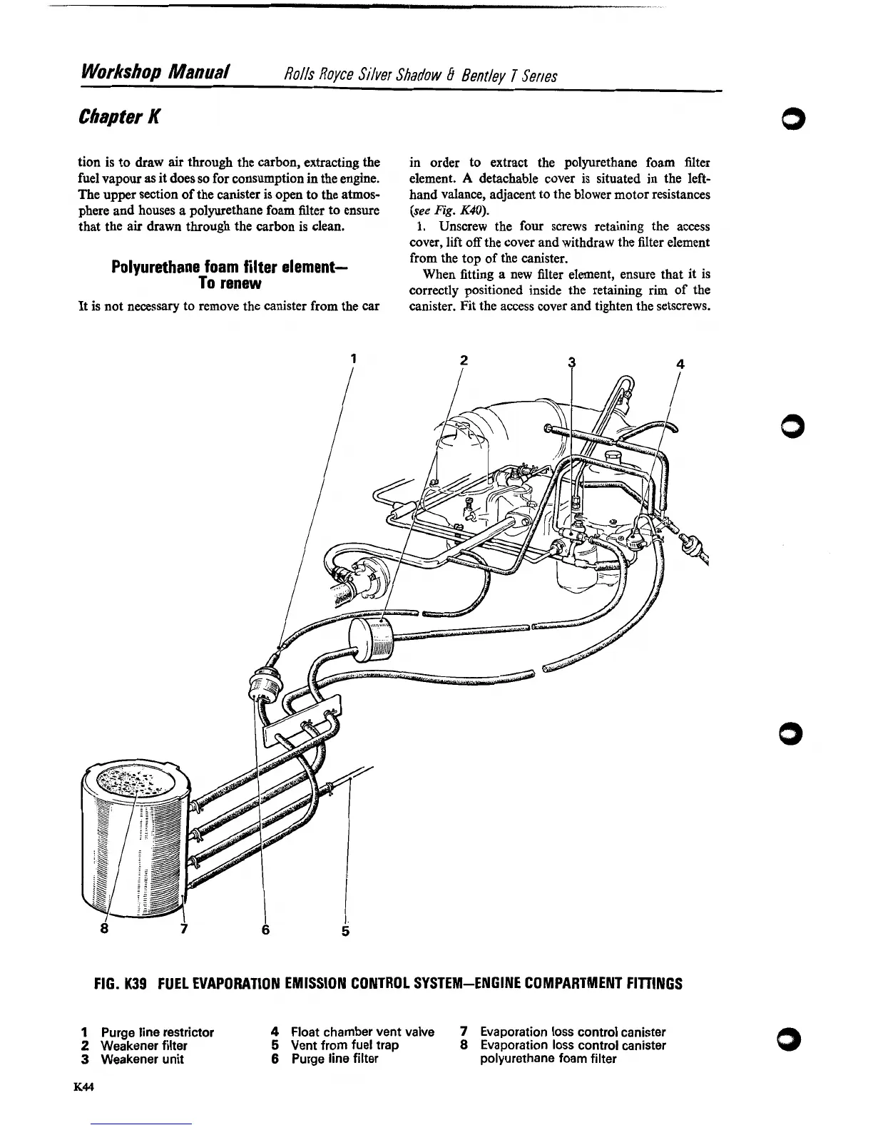
FIG.
K39
FUEL EVAPORATION EMISSION CONTROL SYSTEM-ENGINE COMPARTMENT FITTINGS
1
Purge line restrictor
4
Float chamber vent valve
7
Evaporation loss control canister
2
Weakener filter
5
Vent from fuel trap
8
Evaporation loss control canister
3
Weakener unit
6
Purge line filter
polyurethane foam filter