Workshop
Manual
Rolls Royce Silver Shadow
6
Bentley
T
Ser~es
Chapter
N
2. Lubricate the new valve spool damping
'0'
ring
5.
Slide the spool spring over the stub shaft and,
seal with the approved power steering fluid and insert
using a small screwdriver, ease the spool spring down
the seal into the valve spool groove.
until it is seated in the stub shaft groove.
3. Insert the stub shaft into the valve body, aligning
6.
Lubricate the new cap-to-worm
'0'
ring seal with
the groove in the valve cap with the pin in the valve the approved power steering fluid and insert it into
body
(see
Fig.
N34).
Tap lightly on the cap with a hide
the valve body.
mallet until the cap is against the shoulder in the
Note
Do not
fit
the upper thrust bearing
valve body, with the valve body pin in the cap groove. assembly to the valve assembly at
tais
Hold these parts together during the remainder of the stage.
assembly procedure.
4.
Lubricate the valve spool with the approved
Rocking shah gear and rocking shaft cover-
power steering fluid and slide the spool over the stub
TO inspect
shaft with the notch towards the valve body. Align
the notch with the spool drive pin in the cap groove
1.
Inspect the rocking shaft bearing surface in the
stub and carefully engage the spool in the valve body
rocking shaft cover for excessive wear or scoring. If
bore.
badly worn or scored, renew the rocking shaft cover.
Note
Because the clearance between the spool
2.
Examine the rocking shaft sector teeth and
and valve body is very fine, extreme care
bearing and the seal surface.
If
excessiv'ely worn,
must be taken when assembling these
pitted or scored, renew the rocking shaft.
-
parts. Push the spool evenly and slowly,
with a slight twisting motion, until it
3. Check the rocking shaft for excessive wear or for
reaches the drive pin. Rotate the spool
a broken spring as follows.
slowly with pressure until the notch
en-
4.
Clamp the rocking shaft in a vice.
gages the pin. Before pushing the spool
completely in, make sure that the damp-
ing
'0'
ring seal is evenly distributed in
the spool groove. Slowly push the spool
completely in, taking care not to cut or
pinch the
'0'
ring seal by inserting the
spool beyond its normal position.
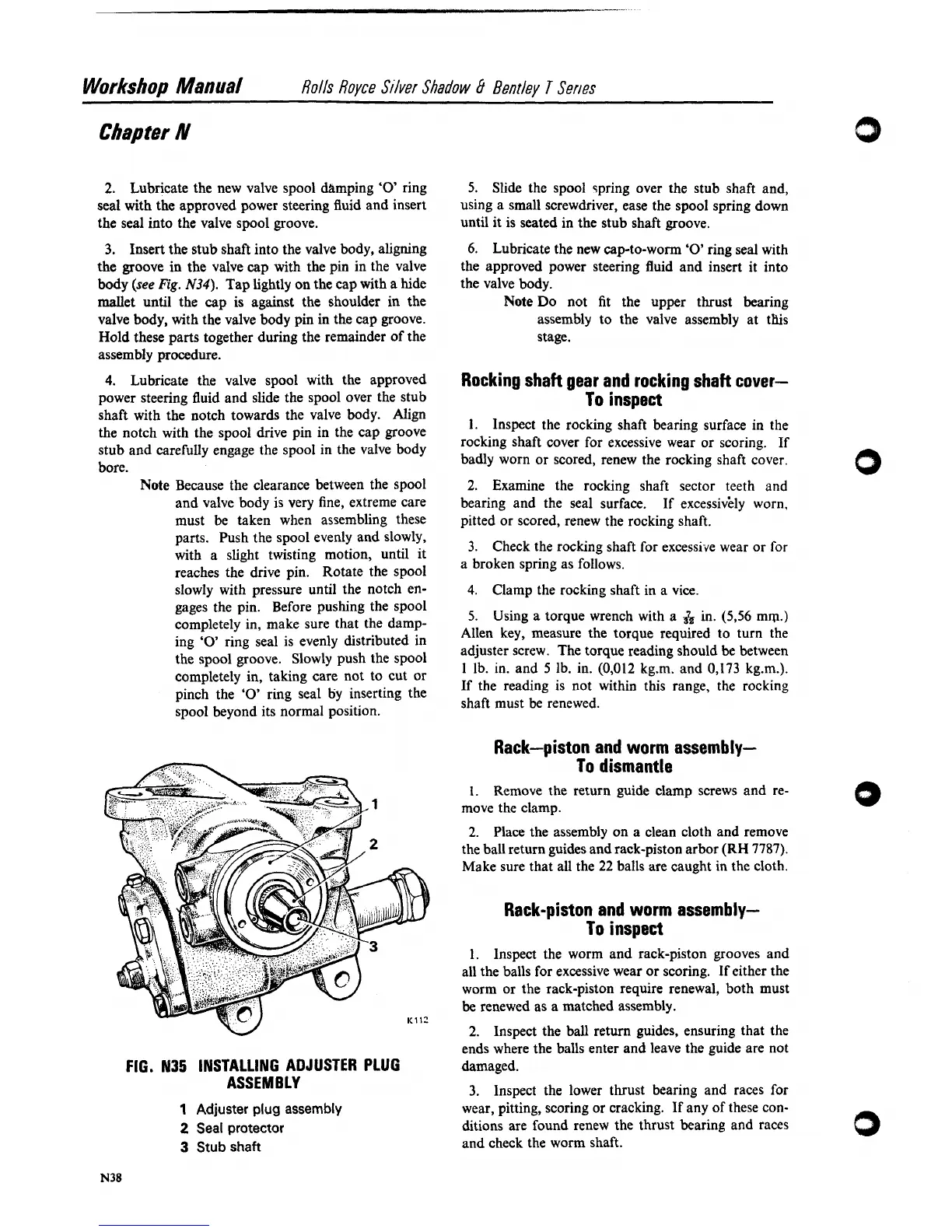
FIG.
N35
INSTALLING ADJUSTER PLUG
ASSEMBLY
1
Adjuster plug assembly
2
Seal protector
3
Stub
shaft
5.
Using a torque wrench with a
&
in.
(5,56
mm.)
Allen key, measure the torque required to turn the
adjuster screw. The torque reading should be between
1
lb. in. and
5
lb. in. (0,012 kg.m. and 0,173 kg.m.).
If the reading is not within this range, the rocking
shaft must be renewed.
Rack-piston and worm assembly-
To dismantle
1.
Remove the return guide clamp screws and re-
move the clamp.
2.
Place the assembly on a clean cloth and remove
the ball return guides and rack-piston arbor (RH 7787).
Make sure that all the
22
balls are caught in the cloth.
Rack-piston and worm assembly-
To inspect
1.
Inspect the worm and rack-piston grooves and
all the balls for excessive wear or scoring. If either the
worm or the rack-piston require renewal, both must
be renewed as a matched assembly.
2.
Inspect the ball return guides, ensuring that the
ends where the balls enter and leave the guide are not
damaged.
3.
Inspect the lower thrust bearing and races for
wear, pitting, scoring or cracking. If any of these con-
ditions are found renew the thrust bearing and races
and check the worm shaft.