Rolls-Royce
Silver
Shadow
8
Bentley
T
Series
Workshop
Manual
Chapter
N
3.
Examine and renew
if
necessary, the two rubber
bushes of the lower support bracket and ensure that
the distance tube is fitted.
4.
Examine the large circlip and groove into which
it seats at the base of the column. The circlip and
groove must be clean and free of paint, the circlip
should be checked in the groove to see that it will seat
correctly.
5.
Fit the column through the rubber grommet in
the toe-board. Take extra care not to knock either
end of the
inner column, thus causing possible damage
c
to the injected plastic rivets, rendering the column
cl
userviceable.
~i
6:
Take the weight of the column by fitting the two
cd
screws of the upper mounting bracket with a washer
-
M
5
fitted to each side of the capsule. Pass the screws
E
.-
through the respective capsules and distance tubes
3
and locate and finger tighten the tapped plate.
i
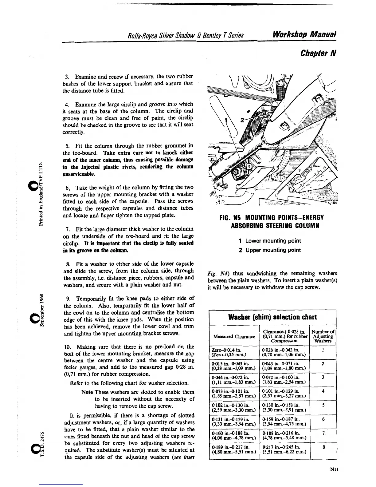
FIG. N5 MOUNTING POINTS-ENERGY
7.
Fit the large diameter thick washer to the column
ABSORBING STEERING COLUMN
on the underside of the toe-board and fit the large
circlip. It is important that the circlip is
fully
seated
1
Lower mounting point
in
its
groove
on
the
column.
2
Upper mounting point
8. Fit a washer to either side of the lower capsule
and slide the screw, from the column side, through
Fig.
N4)
thus
sandwiching
the remaining
the assembly, i.e. distance piece, rubbers, capsule and
between the plain washers.
T~
insert a plain washer(s)
washers, and secure with a plain washer and nut.
it will
be
necessary to withdraw the cap screw.
m
\O
2
9.
Temporarily fit the knee pads to either side of
8
the column. Also, temporarily fit the lower half of
the cowl on to the column and centralise the bottom
o[
edge of this with the knee pads. When this position
IA
has been achieved, remove the lower cowl and trim
and tighten the upper mounting bracket screws.
10.
Making sure that there is no pre-load on the
bolt of the lower mounting bracket, measure the gap
between the centre washer and the capsule using
feeler gauges, and add to the measured gap
0-28 in.
(0,71
mm.)
for rubber compression.
Refer to the following chart for washer selection.
I
Note These washers are slotted to enable them
I
to be inserted without the necessity of
having to remove the cap screw.
It is permissible, if there is a shortage of slotted
adjustment washers, or, if a large quantity of washers
have to be fitted, that a plain washer similar to the
ones fitted beneath the nut and head of the cap screw
be substituted for every two adjusting washers re-
quired. The substitute
washer(s) must be situated at
the capsule side of the adjusting washers
(see
inset
Washer (shim) selection chart
Number
of
Adjusting
Washers
1
2
3
4
5
6
7
8
Measured
Clearance
Zero4014 in.
I
(Zer0-0~35
mm.)
0.015 in.4.043 in.
(0,38 mm.-1,09
mm)
0.044
in.4072 in.
(1,ll mm.-1,83 mm.)
0.073 in.4.101 in.
(1,85 mm.-2,57 mm.)
0.102 in.4.130 in.
(2.59
mm.-3,30
mm.)
0.131 in.4159 in.
(3,33 mm.-3,94 mm.)
0-160 in.4188
in.
(4.06 mm.4,78
mm.)
0-189 in.4.217 in.
(4,80
mm.-$51 mm.)
Clearance+0.028
in.
(0.71 Cornpress~on mm.)
for
rubber
0.028 in.--0.042 in.
(0,70 mm.-1,M mm.)
0.043 in.4071 in.
(1,W mm.-1.80
rnrn.)
0.072 in.4.100 in.
(1.83
mt11.-2,54 mm.)
0.101 in.4129 in.
(237 mm.-3,27
mm.)
0.130 in.4158 in.
(3,30 mm.-3.91 mm.)
0.159 in.4.187 in.
(3,94 mm.4.75 mm.)
0.188 in.4.216 in.
(4,78 mm.-5,48
mm.)
0.217 in.4245
in.
(5,51 mm.-6,22 mm.)