Workshop Manual
Rolls Royce Silver Shadow
8
Bentley
7
Serles
Chapter
N
7.
The fluid level indicated on the filler cap dip-
stick should be raised to the
'FULL'
mark by the
addition of more fluid. Do not overfill. Fit the filler
cap.
Note
(1) If the fluid level in the reservoir rises
more than
4
in.
(6,35
mm.)
when the
engine is switched 'off', some residual
air is present in the system and the
bleeding operation should
be
repeated.
(2)
Considerable heat is generated
in
the
steering system during the bleeding
operation therefore it should not
be
prolonged for more than
5
minutes.
Steering system hoses and pipes
Right-hand drive cars
(see
fig.
N21)
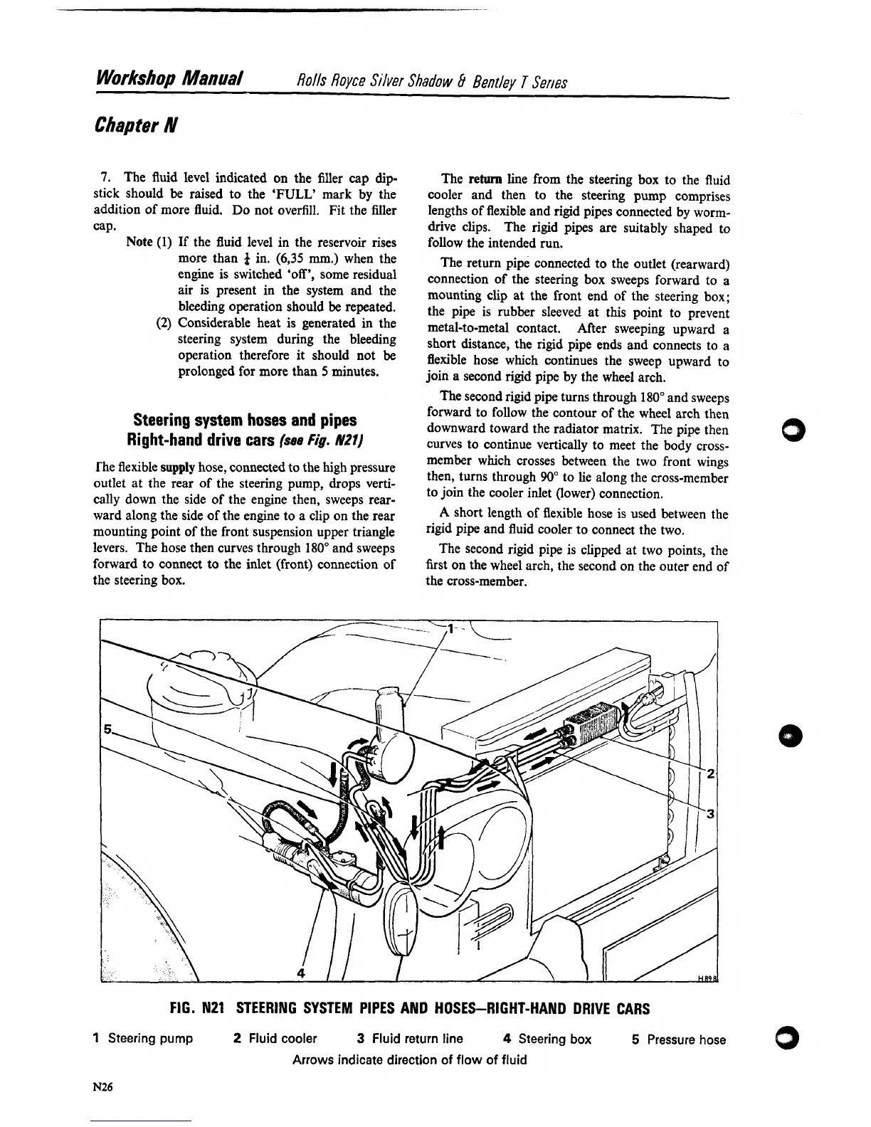
The flexible
supply
hose, connected to the high pressure
outlet at the rear of the steering pump, drops verti-
cally down the side of the engine then, sweeps rear-
ward along the side of the engine to a clip on the rear
mounting point of the front suspension upper triangle
levers. The hose then curves through 180" and sweeps
forward to connect to the inlet (front) connection of
the steering box.
The
return
line from the steering box to the fluid
cooler and then to the steering pump comprises
lengths of flexible and rigid pipes connected by
worm-
drive clips. The rigid pipes are suitably shaped to
follow the intended run.
The return pipe connected to the outlet (rearward)
connection of the steering box sweeps forward to a
mounting clip at the front end of the steering box;
the pipe is rubber sleeved at this point to prevent
metal-to-metal contact. After sweeping upward a
short distance, the rigid pipe ends and connects to
a
flexible hose which continues the sweep upward to
join a second rigid pipe by the wheel arch.
The second rigid pipe turns through
180" and sweeps
forward to follow the contour of the wheel arch then
downward toward the radiator matrix. The pipe then
curves to continue vertically to meet the body
cross-
member which crosses between the two front wings
then, turns through
90"
to lie along the cross-member
to join the cooler inlet (lower) connection.
A
short length of flexible hose is used between the
rigid pipe and fluid cooler to connect the two.
The second rigid pipe is clipped at two points, the
first on the wheel arch, the second on the outer end of
the cross-member.
FIG. N21
STEERING SYSTEM PIPES
AND
HOSES-RIGHT-HAND DRIVE CARS
1
Steering pump
2
Fluid cooler
3
Fluid return line
4
Steering box
5
Pressure hose
0
Arrows indicate direction of flow of fluid