Rolls-K'jyce Silver Shadow
8
Bentley
T
Series
Workshop
Manual
Exhaust manifolds
-
To remove
1.
Support the
downtake pipes just forward of
the front
silencer(s) with wood blocks and jacks.
2.
Slacken and remove the bolts to the
'A'
and
'B'
bank downtake to manifold, spherical joints.
Remove the clamps.
3.
If fitted remove the two choke stove pipes
from the unions located on
'B'
bank manifold.
Blank off the pipes to prevent ingress of dirt
(see
Fig.
Q2
and
Qll).
4.
Remove the setscrews and distance pieces
securing the manifolds to the cylinder heads, then
detach the manifolds, taking care to retain the
sealing rings from the
downtake joints.
5.
Discard the joints fitted between the mani-
folds and the cylinder heads.
6.
Using a flat scraper remove all traces of
carbon from the machined faces of the exhaust
manifolds and the exhaust port faces on the
cylinder heads. Extra care must be taken when
scraping the cylinder heads not to damage the
faces of the aluminium.
7.
Blank off the ports in the cylinder heads to
prevent the ingress of dirt and other foreign matter.
Note
The manifolds have
1,3
cm.
(0.50
in.) long slotted
holes on numbers 1,
2
and
4
flange faces on
'B'
bank and numbers 1,
3
and
4
flange faces on
'A'
bank. These holes allow for normal expansion and
contraction without manifold distortion
(see
Fig.
Q12
inset).
Exhaust manifolds
-
To inspect
1.
The exhaust manifold should be checked for
distortion by applying a straight edge across the
joint face. Small irregularities should be corrected
by dressing the face using abrasive cloth.
Note
Before re-facing, any scale on the joint faces
should be carefully removed with a medium-cut
file.
The importance of the
manifold faces being flat
and square cannot be over-emphasised.
Chapter
Q
Section
Q4
EXHAUST MANIFOLDS
Exhaust manifolds
-
To
fit
To fit the manifolds, reverse the procedure given
for their removal noting the following points.
1. Ensure all joint faces are free from scale
1
2
4
3
S
492
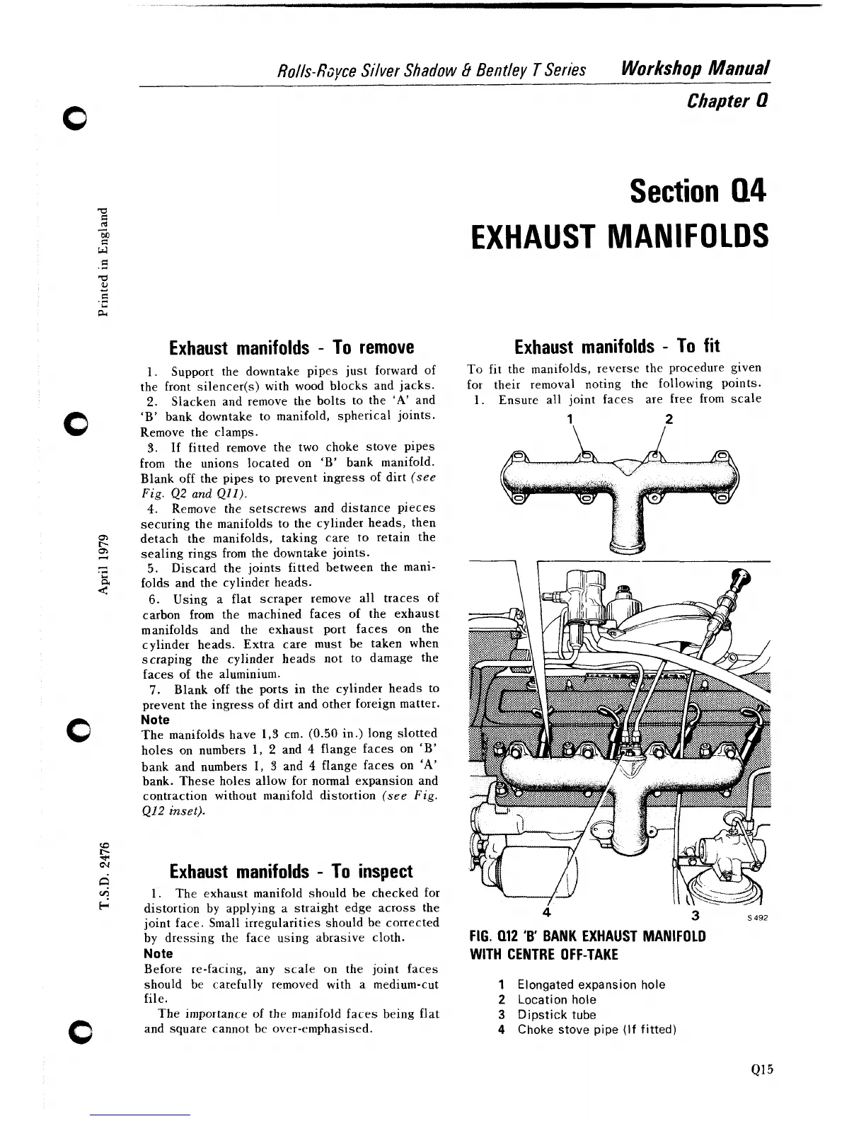
FIG.
Q12
'B'
BANK EXHAUST MANIFOLD
WITH CENTRE OFF-TAKE
1
Elongated expansion hole
2
Location hole
3
Dipstick tube
4
Choke stove pipe (If fitted)