Workshop
Manual
Rolls Royce Silver Shadow
8
Bentley
T
Series
Chapter
N
Gearchange selector switch-To fit
1.
Fit the gearchange selector switch onto the
steering column taking care to locate the switch dowel
in the hole provided.
Note
To facilitate assembly it is advisable to
place the bottom cowl clamp on the
steering column before tightening the
selector switch assembly.
2.
Connect the insulating pad and contact assembly,
the
micro-switch(es) and the indicator lamp wiring.
3.
Fit the lower half of the cowling onto its clamp-
ing bracket then fit the upper half of the cowling.
Note
Care must
be
taken before tightening the
cowling retaining screws to ensure that
the wiring looms are not trapped between
the cowl and cover.
Direction indicator switch-To remove
1.
Disconnect the battery.
2.
Remove the gearchange selector switch as des-
cribed previously.
3.
Disconnect the wiring loom.
4.
Remove the two Allen screws securing the switch
clamp to the column; remove the switch.
Direction indicator switch-To fit
1.
To fit the direction indicator switch reverse the
procedure given for its removal.
Note The indicator switch has a dowel in its
base which locates in the steering column
tube.
Upper steering column-To dismantle
1.
Remove the steering wheel gearchange selector
and direction indicator switch as previously described.
2.
Remove the two screws securing the horn con-
tact brush assembly to the column then remove the
assembly.
3.
Remove the screw securing the earth contact
strip to the column then remove the strip.
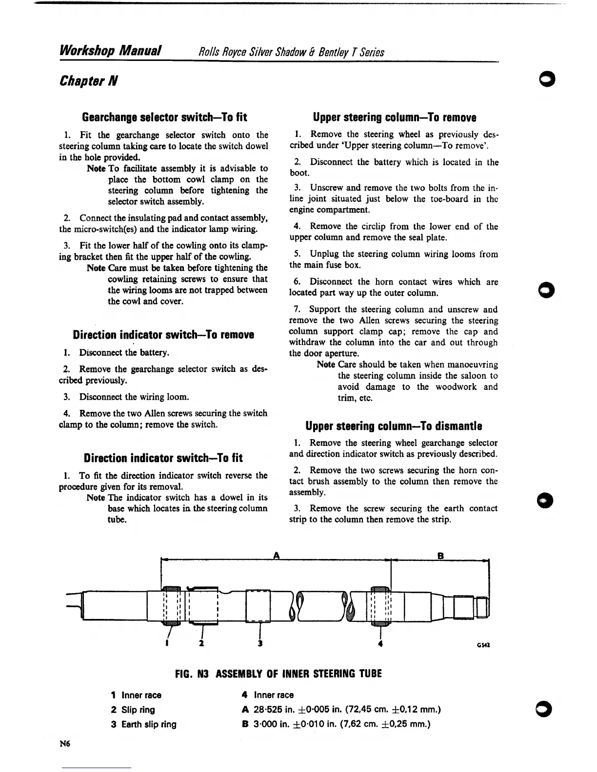
FIG. N3 ASSEMBLY
OF
INNER STEERING TUBE
1
lnner race
2
Slip ring
3
Earth slip ring
4
lnner race
A
28.525 in.
f
0.005 in. (72,45
cm.
f
0.1 2
mm.)
B
3-000 in.
f
0.010 in. (7,62
cm.
f
0,25
mm.)
Upper steering column-To remove
I.
Remove the steering wheel as previously des-
cribed under 'Upper steering column-To remove'.
2.
Disconnect the battery which is located in the
boot.
3.
Unscrew and remove the two bolts from the in-
line joint situated just below the toe-board in
the
engine compartment.
4.
Remove the circlip from the lower end of the
upper column and remove the seal plate.
5.
Unplug the steering column wiring looms from
the main fuse box.
6.
Disconnect the horn contact wires which are
located part way up the outer column.
7.
Support the steering column and unscrew and
remove the two Allen screws securing the steering
column support clamp cap; remove the cap and
withdraw the column into the car and out through
the door aperture.
Note
Care should be taken when manoeuvring
the steering column inside the saloon to
avoid damage to the woodwork and
trim, etc.