Workshop Manual
Rolls Royce Silver Shadow
B
Bentley
T
Series
Chapter
K
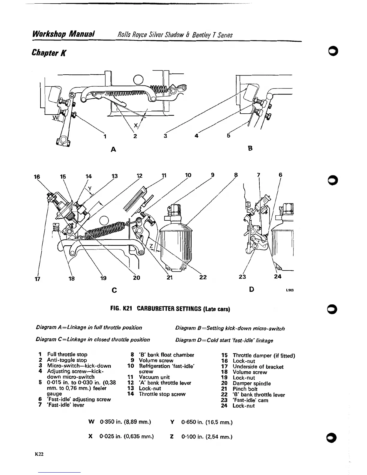
FIG.
K21
CARBURElTER SETTINGS
(Late
cars)
Diagram A=Linkage in full throttle position
Diagram
B
=Setting kick-do wn micro -switch
Diagram
C=L
inkage in closed throttle position
Diagram
D
=
Cold start 'fast-idle
'
linkage
1
Full throttle stop
8
'6'
bank float chamber
15
Throttle damper (if fitted)
2
Anti-toggle stop
9
Volume screw
16
Lock-nut
3
Micro-switch-kick-down
10
Refrigeration 'fast-idle'
17
Underside of bracket
4
Adjusting screw-kick- screw
18
Volume screw
down micro-switch
11
Vacuum unit
19
Lock-nut
5
0.01 5 in. to 0.030 in. (0,38
12
'A'
bank throttle lever
20
Damper spindle
mm. to 0.76 mm.) feeler 13 Lock-nut
21
Pinch bolt
gauge
14
Throttle stop screw
22
'6'
bank throttle lever
6
'Fast-~dle' adjusting screw
23
'Fast-idle' cam
7
'Fast-idle' lever
24
Lock-nut
W
0.350 in. (8,89 mm.)
Y
0.650 in.
(1
6,5 mm.)
X
0.025 in. (0,635 mm.)
Z
0.100 in. (2,54 mm.1