Workshop
Manual
Rolls- Royce Silver Shadow
8
Bentlev
T
Series
Chapter
M
FIG. M24 CHARGING CIRCUIT VOLTAGE DROP TESTING
-
INSULATION SlDE
FIG. M25 CHARGING CIRCUIT VOLTAGE DROP TESTING
-
EARTH SlDE
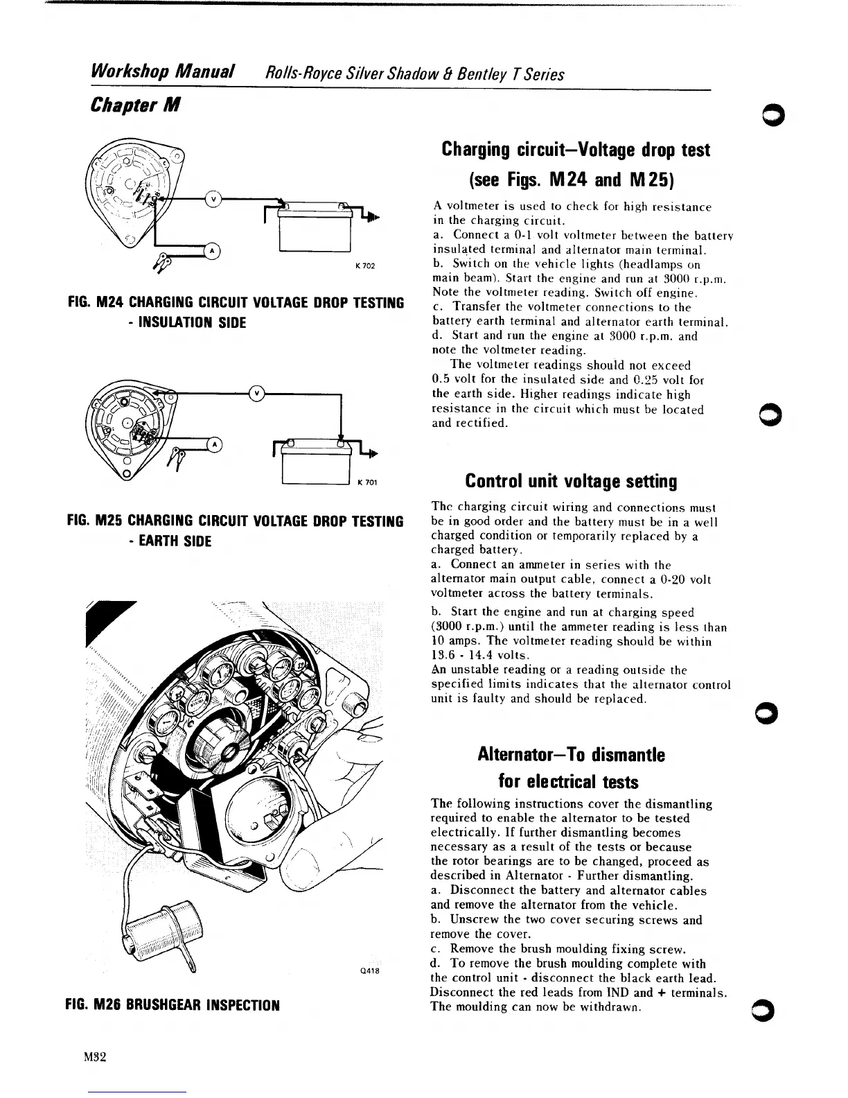
FIG. M26 BRUSHGEAR INSPECTION
Charging circuit-Voltage drop test
(see Figs.
M
24
and
M
25)
A
voltmeter is used to check for high resistance
in the charging circuit.
a. Connect a 0-1 volt voltmeter between the battery
insulated terminal and alternator main terminal.
b. Switch on the vehicle lights
(headlamps on
main beam). Start the engine and run at 3000
r.p.rn.
Note the voltmeter reading. Switch off engine.
c. Transfer the voltmeter connections to the
battery earth terminal and alternator earth terminal.
d. Start and run the engine at 3000
r.p.m. and
note the voltmeter reading.
The voltmeter readings should not exceed
0.5
volt for the insulated side and
C.25
volt for
the earth side. Higher readings indicate high
resistance in the circuit which must be located
and rectified.
Control unit voltage setting
Thc charging circuit wiring and connectio~s must
be in good order and the battery must be in a well
charged condition or temporarily replaced by a
charged battery.
a. Connect an ammeter in series with the
alternator main output cable, connect a 0-20 volt
voltmeter across the battery terminals.
b.
Start the engine and run at charging speed
(3000
1.p.m.) until the ammeter reading is less than
10 amps. The voltmeter reading should be within
13.6
-
14.4
volts.
An unstable reading or a reading outside the
specified limits indicates that the alternator control
unit is faulty and should be replaced.
Alternator-To dismantle
for electrical tests
The following instructions cover the dismantling
required to enable the alternator to be tested
electrically. If further dismantling becomes
necessary as a result of the tests or because
the rotor bearings are to be changed, proceed as
described in Alternator
-
Further dismantling.
a. Disconnect the battery and alternator cables
and remove the alternator from the vehicle.
b. Unscrew the two cover securing screws and
remove the cover.
c. Remove the brush moulding fixing screw.
d. To remove the brush moulding complete with
the control unit
-
disconnect the black earth lead.
Disconnect the red leads from IND and
+
terminals.
The moulding can now be withdrawn.