Workshop
Manual
Rolls Royce Silver Shadow
6
Bentley
T
Ser~es
Chapter
J
2.
Fit the final drive unit as instructed under 'Final
A
8
drive unit-To fit',
carrying
out Operations
1
to
8,
with the exception of Operation 4, the half-shafts being
left disconnected from the yokes but supported.
3.
With the final drive unit fitted to the cross-
member, a check must now be made to ensure that
the final drive is centrally positioned.
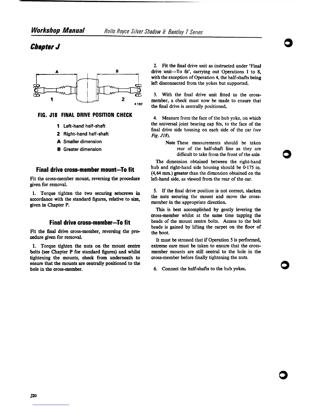
FIG.
518
FINAL DRIVE POSITION CHECK
4. Measure from the face of the hub yoke, on which
1
Left-hand half-shaft
the universal joint bearing cap fits, to the face of the
final drive side housing on each side of the car
(see
2
Right-hand half-shaft
Fig.
J18).
A
Smaller dimension
B
Greater dimension
Note These measurements should be taken
rear of the half-shaft
line as they are
difficult to take from the front of the axle.
The dimension obtained between the right-hand
hub and right-hand side housing should be
0.175
in.
Final
drive
cross-member
mount-To
fit
(444
mm.)
greater than the dimension obtained on the
Fit the cross-member mount, reversing the procedure
left-hand side, as viewed from the rear of the car.
given for removal.
1.
Torque tighten the two securing setscrews
in
accordance with the standard figures, relative to
size,
given
in
Chapter
P.
Final drive cross-member-To fit
Fit the final drive cross-member, reversing the pro-
cedure
given for removal.
1.
Torque tighten the nuts on the mount centre
bolts
(see
Chapter
P
for standard figures) and
whilst
tightening the mounts, check from underneath to
ensure that the mounts are centrally positioned to the
hole in the cross-member.
5.
If the final drive position is not correct, slacken
the nuts securing the mount and move the cross-
member in the appropriate direction.
This is best accomplished by gently levering the
cross-member whilst at the same time tapping the
heads of the mount centre bolts. Access to the bolt
heads is gained by lifting the carpet on the floor of
the boot.
It must be stressed that
if
Operation
5
is performed,
extreme care must be taken to ensure that the cross-
member mounts are still central to the hole in the
cross-member before finally tightening the nuts.
6.
Connect the half-shafts to the hub yokes.