Workshop
Manual
Rolls Royce Silver Shadow
19
Bentley
T
Serles
Chapter
K
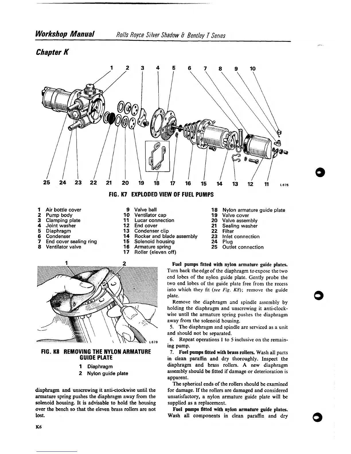
FIG.
K7
EXPLODED VIEW OF FUEL PUMPS
1
Air bottle cover
2
Pump body
3
Clamping plate
4
Joint washer
5
Diaphragm
6
Condenser
7
End cover sealing ring
8
Ventilator valve
9
Valve ball
10
Ventilator cap
11
Lucar connection
12
End cover
13
Condenser clip
14
Rocker and blade assembly
15
Solenoid housing
16
Armature spring
17
Roller (eleven off)
Nylon armature guide plate
Valve cover
Valve assembly
Sealing washer
Filter
Inlet connection
Plug
Outlet connection
FIG.
K8
REMOVING THE NYLON ARMATURE
GUIDE PLATE
1
Diaphragm
2
Nylon guide plate
diaphragm and unscrewing it
anti-clockwise until the
armature spring pushes the diaphragm away from the
solenoid housing.
It
is advisable to hold the housing
over the bench so that the eleven brass rollers are not
lost.
Fuel pumps fitted with nylon armature guide plates.
Turn back
theedge of the diaphragm to expose the two
end lobes of the nylon guide plate. Gently probe the
two end lobes of the guide plate free from the recess
into which they fit
(see
Fig.
K8);
remove the guide
plate.
Remove the diaphragm and spindle assembly by
holding the diaphragm and unscrewing it anti-clock-
wise until the armature spring pushes the diaphragm
away from the solenoid housing.
5.
The diaphragm and spindle are serviced as a unit
and should not be separated.
6.
Repeat operations
1
to
5
inclusive on the remain-
ing pump.
7.
Fuel pumps
fitted
with brass rollers. Wash all parts
in clean paraffin and
dry thoroughly. Inspect the
diaphragm and brass rollers.
A
new diaphragm
assembly should be fitted if damage or deterioration is
apparent.
The spherical ends of the rollers should
be examined
for damage.
Tf the rollers are damaged and considered
unsatisfactory, a nylon armature guide plate will
be
supplied as a replacement.
Fuel
pumps
fitted
with nylon armature guide plates.
Wash all
coaponents in clean paraffin and dry