Workshop
Manua/
Rolls Royce Silver Shadow
d
Bentley
T
Series
Chapter
IV
5.
Check the condition of the shaft bearing (bush-
ing).
Note
The bearing is rarely, if evzr, responsible
for noisy pump operation.
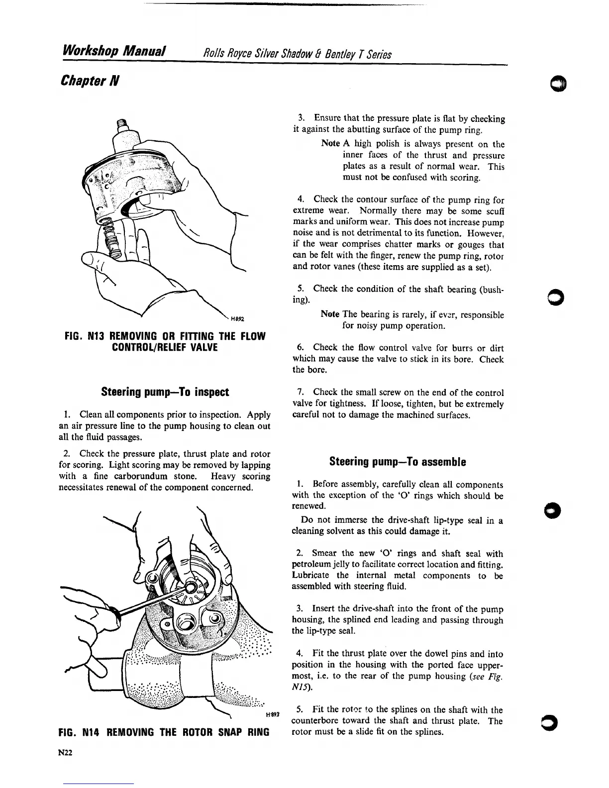
FIG. N13 REMOVING OR FITTING THE FLOW
CONTROL/RELIEF VALVE
Steering pump-To inspect
1.
Clean all components prior to inspection. Apply
an air pressure line to the pump housing to clean out
all the fluid passages.
2.
Check the pressure plate, thrust plate and rotor
for scoring. Light scoring may
be
removed by lapping
with a fine carborundum stone. Heavy scoring
necessitates renewal of the component concerned.
H.893
FIG. N14 REMOVING THE ROTOR SNAP RING
3.
Ensure that the pressure plate is flat by checking
it against the abutting surface of the pump ring.
Note
A
high polish is always present on the
inner faces of the thrust and pressure
plates as a result of normal wear. This
must not be confused with scoring.
4.
Check the contour surface of the pump ring for
extreme wear.
Normally there may be some scuff
marks and uniform wear. This does not increase pump
noise and is not detrimental to its function. However,
if the wear comprises chatter marks or gouges that
can be felt with the finger, renew the pump ring, rotor
and rotor vanes (these items are supplied as a set).
6.
Check the flow control valve for burrs or dirt
which may cause the valve to stick in its bore. Check
the bore.
7.
Check the small screw on the end of the control
valve for tightness. If loose, tighten, but be extremely
careful not to damage the machined surfaces.
Steering pump-To assemble
1.
Before assembly, carefully clean all components
with the exception of the
'0'
rings which should be
renewed.
Do not immerse the drive-shaft lip-type seal in
a
cleaning solvent as this could damage it.
2.
Smear the new
'0'
rings and shaft seal with
petroleum jelly to facilitate correct location and fitting.
Lubricate the internal metal components to be
assembled with steering fluid.
3.
Insert the drive-shaft into the front of the pump
housing, the splined end leading and passing through
the lip-type seal.
4.
Fit the thrust plate over the dowel pins and into
position in the housing with the ported face upper-
most,
i.e. to the rear of the pump housing
(see
Fig.
NIS).
5.
Fit the rotnr to the splines on the shaft with the
counterbore toward the shaft and thrust plate. The
rotor must be a slide fit on the splines.