Workshop
Manual
Rolls Royce Silver Shadow
d
Bentley
T
Series
Chapter
N
2.
Inspect the high and low pressure line hose
connector seats, the poppet valve and seat in the
steering box housing. Renew if they are badly scored,
cracked or distorted.
3.
Inspect the ball plug in the valve body end of the
housing. If it is leaking or raised above the surface
it should be seated flush or
&
in. (1,59
rnm.)
below
the surface.
Lightly
peen over the end of the bore to
secure the ball.
2.
Tap threads in the connector seats using a
I$
in.
thread tap.
Note
Do not tap threads too deeply in the
pressure hose connector seat as the tap
will bottom the poppet valve against the
housing and damage it. It is necessary
to tap only
2
or
3
threads deep.
3. Insert a
&
in. threaded bolt with a nut and
suitable flat washer into the tapped hole (see
Fig.
N27).
4.
To extract the connector seat, prevent the bolt
4.
Inspect all retaining ring grooves and seal sur-
from rotating while screwing the nut off the bolt. This
faces for damage or failure.
will extract the connector from the housing. Discard
the connector seat.
Hose connectors-To remove
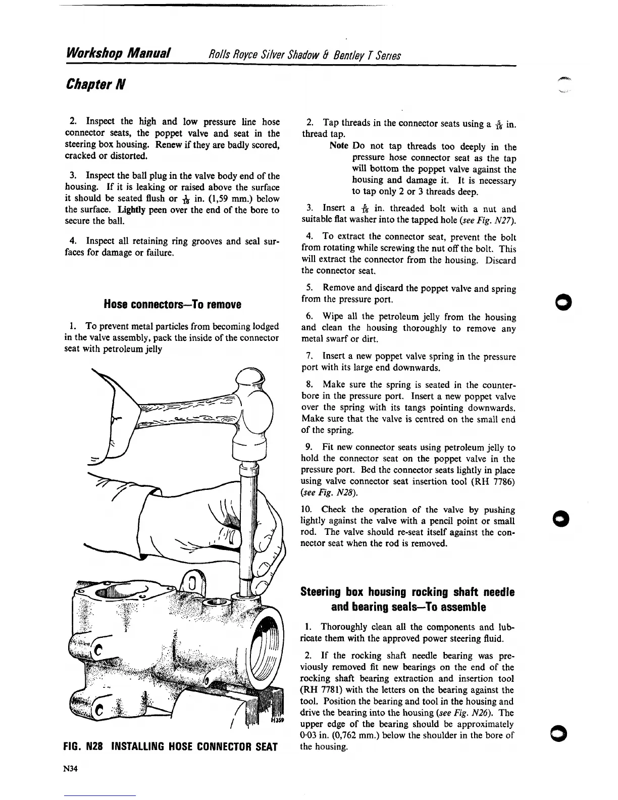
1. To prevent metal particles from becoming lodged
in the valve assembly, pack the inside of the connector
seat with petroleum jelly
FIG. N28 INSTALLING HOSE CONNECTOR SEAT
5.
Remove and discard the poppet valve and spring
from the pressure port.
6.
Wipe all the petroleum jelly from the housing
and clean the housing thoroughly to remove any
metal swarf or dirt.
7.
Insert a new poppet valve spring in the pressure
port with its large end downwards.
8.
Make sure the spring is seated in the counter-
bore in the pressure port. Insert
a
new poppet valve
over the spring with its tangs pointing downwards.
Make sure that the valve is centred on the small end
of the spring.
9. Fit new connector seats using petroleum jelly to
hold the connector seat on the poppet valve in the
pressure port. Bed the connector seats lightly in place
using valve connector seat insertion tool
(RH
7786)
(see
Fig.
N28).
10. Check the operation of the valve by pushing
lightly against the valve with a pencil point or small
rod. The valve should re-seat itself against the con-
nector seat when the rod is removed.
Steering box housing rocking shaft needle
and bearing seals--To assemble
1.
Thoroughly clean all the components and lub-
ricate them with the approved power steering fluid.
2.
If the rocking shaft needle bearing was pre-
viously removed fit new bearings on the end of the
rocking shaft bearing extraction and insertion tool
(RH
7781)
with the letters on the bearing against the
tool. Position the bearing and tool in the housing and
drive the bearing into the housing (see
Fig.
N26).
The
upper edge of the bearing should be approximately
0.03 in. (0,762 mm.) below the shoulder in the bore of
the housing.
0