Workshop
Manual
Rolls Royce
Silver
Shadow
b
Bentlev
i
Series
6.
Pull
the gear bask out of mesh as far as possible
and again measure from the end of the housing to the
end of the gear (see
Fig.
J4).
The difference between these two measurements
will
give the nominal size of adjusting washer required
behind the gear head.
7.
Dismantle the gears and then assemble them
with the correct adjusting washer fitted behind the
bevel pinion.
Adjusting washers are available in a range from
0.084 in. to 0.116 in.
(2,13
mm.
to
2,94
mm.)
in
0.002
in. (0,05
mm.)
increments and they must be fitted with
the chamfer and the oil grooves against the back face
of the gear.
8.
Rotate the gears to ensure that they are perfectly
free, but without backlash, if necessary vary the
thickness of the adjusting washer.
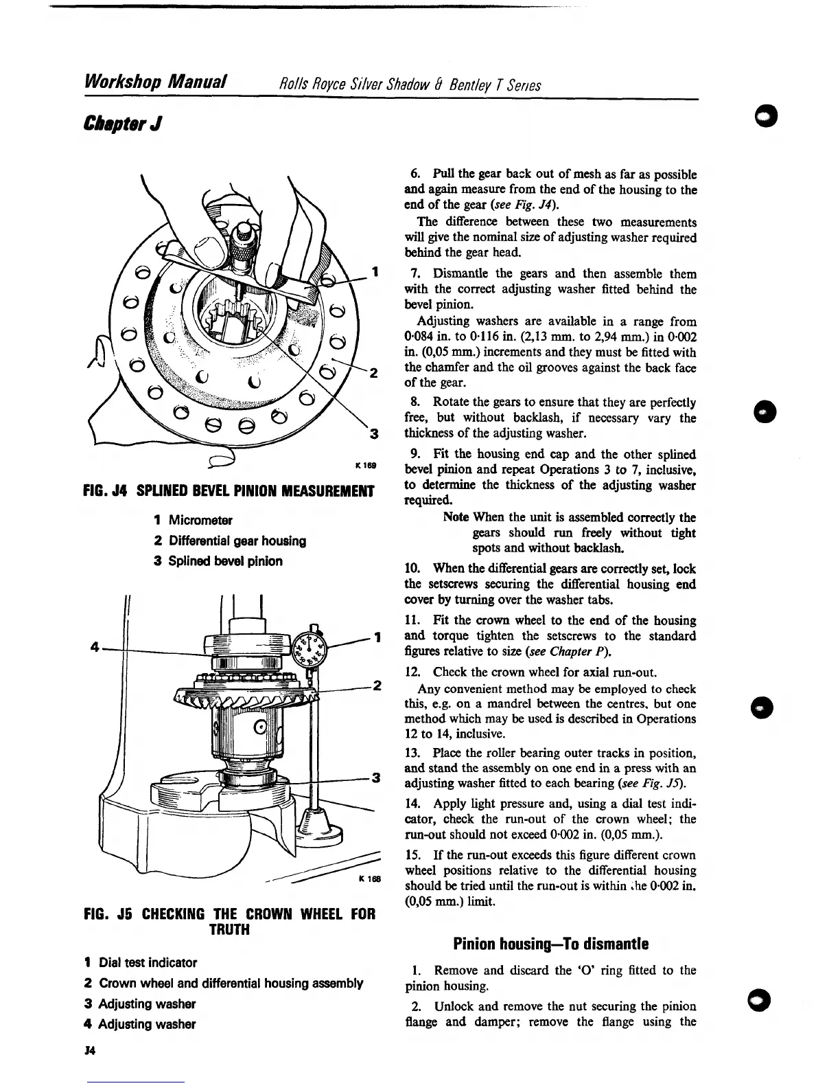
FIG.
J4
SPUNED BEVEL PINION MEASUREMENT
1
Micrometer
2
Differential gear housing
3
Splined bevel pinion
ILL
FIG.
55
CHECKING THE CROWN WHEEL
FOR
TRUTH
1
Dial test indicator
2
Crown wheel and differential housing assembly
3
Adjusting washer
4
Adjusting washer
9.
Fit the housing end cap and the other splined
bevel pinion and repeat Operations 3 to
7,
inclusive,
to determine the thickness of the adjusting washer
required.
Note
When the unit is assembled correctly the
gears should
run
freely without tight
spots and without backlash.
10. When the differential gears
are
correctly set, lock
the setscrews securing the differential housing end
cover
by
turning over the washer tabs.
11. Fit the crown wheel to the end of the housing
and torque tighten the setscrews to the standard
figures relative to size (see Chapter
P).
12.
Check the crown wheel for axial run-out.
Any convenient method may
be
employed to check
this,
e.g. on a mandrel between the centres, but one
method which may be used is described in Operations
12
to 14, inclusive.
13. Place the roller bearing outer tracks in position,
and stand the assembly on one end in a press with an
adjusting washer fitted to each bearing (see
Fig.
J5).
14. Apply light pressure and, using
a
dial test indi-
cator, check the run-out of the crown wheel; the
run-out should not exceed
0.002
in.
(0,05
mm.).
15.
If
the run-out exceeds this figure different crown
wheel positions relative to the differential housing
should
be
tried until the run-out is within &he
0.002
in.
(0,05
mm.)
limit.
Pinion housing-To dismantle
1. Remove and discard the
'0'
ring fitted to the
pinion housing.
2.
Unlock and remove the nut securing the pinion
flange and damper; remove the flange using the