Rolls- Royce Silver Shadow
8
Bentley
T
Series
Workshop
Wua/
Chapter
L
Coolant pump
-
To dismantle
1
2
3
For normal service operation, the bearing housing
will have already been separated from the pump
a
casing.
9
A
1.
Draw the impeller off the shaft using the
M
c
special tool (RH 7098).
W
E
2. Remove the peg screw which retains the
.-
bearing in the housing.
-z
,d
3.
Support the bearing housing to enable the
.
a
bearing assembly to be lightly driven out with a
PI
mallet.
4.
Remove and discard the seal and counter
face.
5.
Examine the shaft and bearing for wear and
damage. The assembly contains lubricant there-
fore no attempt must be made to wash any of the
components.
6.
If the
spider
(early cars),
flange
(later cars)
or the shaft has been damaged, draw the component
off the shaft using the following special tool.
S
583
Spider
-
(RH 7099)
Flange
-
(RH 8615)
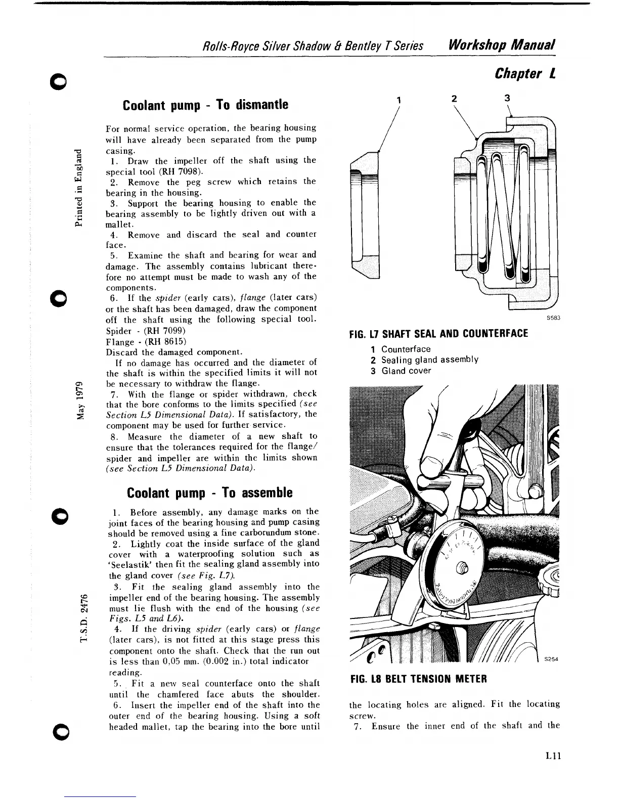
FIG. 17 SHAFT SEAL AND COUNTERFACE
Discard the damaged component.
1
Counterface
If no damage has occurred and the diameter of
2
Sealing gland assembly
the shaft is within the specified limits it will not
3
Gland cover
be necessary to withdraw the flange.
7.
With the flange or spider withdrawn, check
that the bore conforms to the limits specified
(see
Section
L5
Dimensional Data).
If satisfactory, the
component may be used for further service.
8. Measure the diameter of a new shaft to
ensure that the tolerances required for the
flange/
spider and impeller are within the limits shown
(see Section
L5
Dimensional Data).
Coolant pump
-
To
assemble
1.
Before assembly, any damage marks on the
joint faces of the bearing housing and pump casing
should be removed using a fine carborundum stone.
2.
Lightly coat the inside surface of the gland
cover with a waterproofing solution such as
'Seelastik' then fit the sealing gland assembly into
the gland cover
(see Fig.
L7).
3.
Fit the sealing gland assembly into the
impeller end of the bearing housing. The assembly
must lie flush with the end of the housing
(see
Figs.
L5
and
L6).
4.
If
the driving
spider
(early cars) or
flange
(later cars), is not fitted at this stage press this
component onto the shaft. Check that the run out
is less than
0,05 mm. (0.002 in.) total indicator
reading.
5.
Fit a new seal counterface onto the shaft
FIG. 18 BELT TENSION METER
until the chamfered face abuts the shoulder.
6.
Insert the impeller end of the shaft into the the locating holes are aligned. Fit the locating
outer end of the bearing housing. Using a soft screw.
headed mallet, tap the bearing into the bore until
7. Ensure the inner end of the shaft and the