Rolls-Royce Silver
Shadow
B
Bentley
T
Series
Workshop
Manual
C
Chapter
M
.3.
.Press the old bearing out of the bracket.
4.
Before fitting the new bearing, ensure that it
is clean and packed with an approved melting-point
grease.
5.
Locate the bearing in the housing and press
C
.
-
n
squarely into position.
-
-
d
6.
When fitting the bearing retaining plate, use
-
*
I
new rivets.
C?
..
Alternator output control unit Model
4
TR
F
E
.-
h
Important
The battery must never be dis-
n.
connected while the alternator is
running. Failure to observe this
ruling will cause the control unit to
be damaged.
Checking and adjusting
1.
Before checking and adjusting the control unit
it must be established that the alternator and the
charging circuit wiring are in good condition.
2.
Check the battery to control unit wiring which
incorporates the field isolating relay. To ensure
correct working of the control unit, the resistance of
this complete circuit, including the isolating relay,
must not exceed
0.1
ohm. Any unduly high resistance
must be traced and rectified.
C
6
-
6
E
$
z
Control unit-To check
Do not disturb the existing connections to the alter-
nator and control unit.
1.
Connect a voltmeter of the suppressed-zero
type, reading
12
Volt to
15
Volt between the battery
terminals and note the reading with all electrical
equipment switched off.
2.
Switch on an electrical load of approximately
2
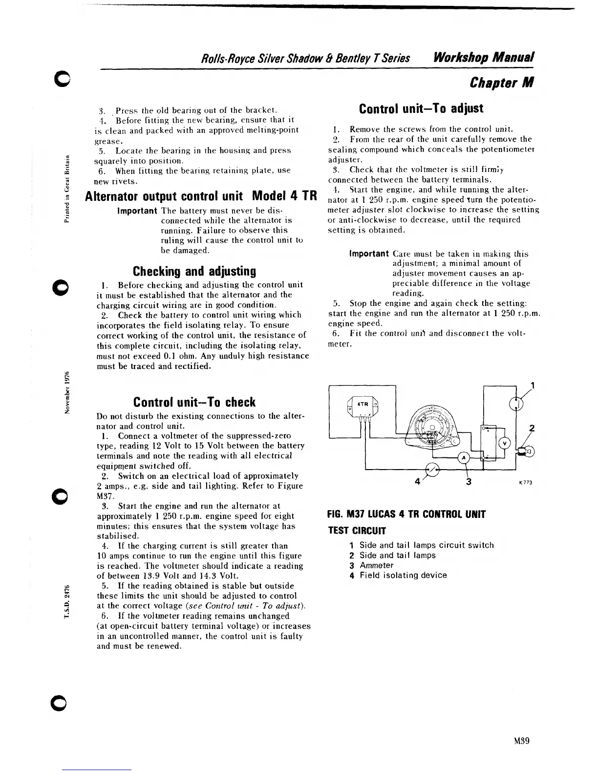
amps., e.g. side and tail lighting. Refer to Figure
0
M37.
3.
Start the engine and run the alternator at
approximately
1
250
r.p.m. engine speed for eight
Control unit-To adjust
1.
Remove the screws from the control unit.
2.
From the rear of the unit carefully remove the
sealing compound which conceals the potentiometer
adjuster.
3.
Check that the voltmeter
is
still firmly
connected between the battery terminals.
,I.
Start the engine, and while running the alter-
nator at
1
250
r.p.m. engine speed.turn the potentio-
meter adjuster slot clockwise to increase the setting
or anti-clockwise to decrease, until the required
setting is obtained.
Important
Care must be taken in making this
adjustment; a minimal amount of
adjuster movement causes an ap-
preciable difference
;n the voltage
reading.
5.
Stop the engine and again check the setting:
start the engine and run the alternator at
1
250
r.p.m.
engine speed.
6.
Fit the control unit and disconnect the volt-
meter.
4'
3
K773
FIG.
M37
LUCAS
4
TR
CONTROL UNIT
minutes; this ensures that the system voltage has
stabilised.
TEST CIRCUIT
4.
If
the charging current is still greater than
1
Side and tail lamps circuit switch
10
amps continue to run the engine until this figure
2
Side and tail lamps
is reached. The voltmeter should indicate a reading
3
Ammeter
of between
13.9
Volt and
14.3
Volt.
4
Field isolating device
iD
I-
3
5.
If the reading obtained is stable but outside
N
these limits the unit should be adjusted to control
?'
at the correct voltage
(see
Control unit
-
To
adjust).
"?
t-
6.
If the voltmeter reading remains unchanged
(at open-circuit battery terminal voltage) or increases
in an uncontrolled manner, the control unit is faulty
and must be renewed.