Rolls- Royce Silver Shadow
&
Bentley
T
Series
Workshop
Manual
Chapter
M
Section
MI2
HORNS
The horns are mounted beneath the left-hand front
The mounting for the
WT7H horns is different
O
wing adjacent to the front of the body underframe.
from that used for the
WT618 horns. Replacement of
a pair of
WT618 horns by a pair of WT7H horns will
necessitate a new mounting (refer to the
S$are Parts
Ltst).
Horns-To remove
1. Disconnect the battery.
2.
Disconnect the leads to the horns.
3.
Remove the four %in.
A/F
setscrews (two per
horn).
4.
Carefully remove the horn(s).
Horns (WT
618
-
Early cars)-To adjust
No adjustments are provided to alter the pitch of the
horn.
A
poor note can be attributed to the condition
of the contact points, insufficiently tightened
mounting brackets or a low voltage at the horns.
To rectify these faults proceed as follows.
1.
Remove the horns as described in Horns
-
To
remove.
2.
Clean the contact points.
3.
Insert an ammeter in series with the horn, and
test with a voltage of
12
Volts at the horn.
4.
Screw in the adjustable contact (see
Fzg.
M85)
until the horn just fails to sound.
5.
Unscrew half-a-turn and lock.
6. Slight re-adjustment may be necessary to
'
tune'
the horn to obtain the correct pitch. The horn should
operate correctly with a minimum voltage of 10 Volts,
at the horn. Remove the ammeter. If the horns still
give a poor note the horn in doubt should be renewed.
Horris (WT 7H
-
Late cars)-To test
The horns (see
Fig.
M86
)
are sealed units and the
only maintenance required is adjustment to the
contacts. These adjustments are effected in a similar
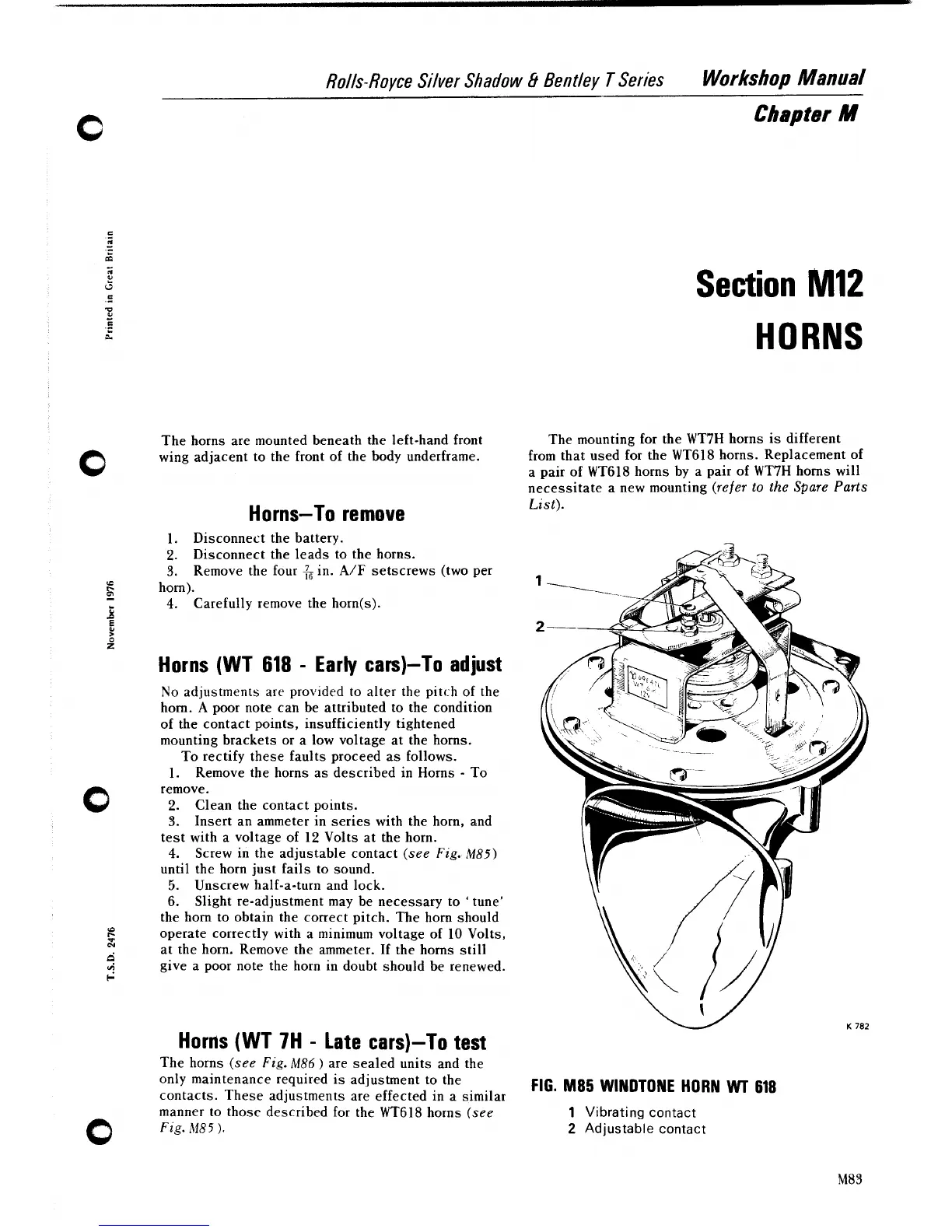
FIG.
M85
WINDTONE HORN
WT
618
manner to those described for the WT618 horns (see
1
Vibrating contact
0
Fig.M85).
2
Adjustable contact