---
K
61
2
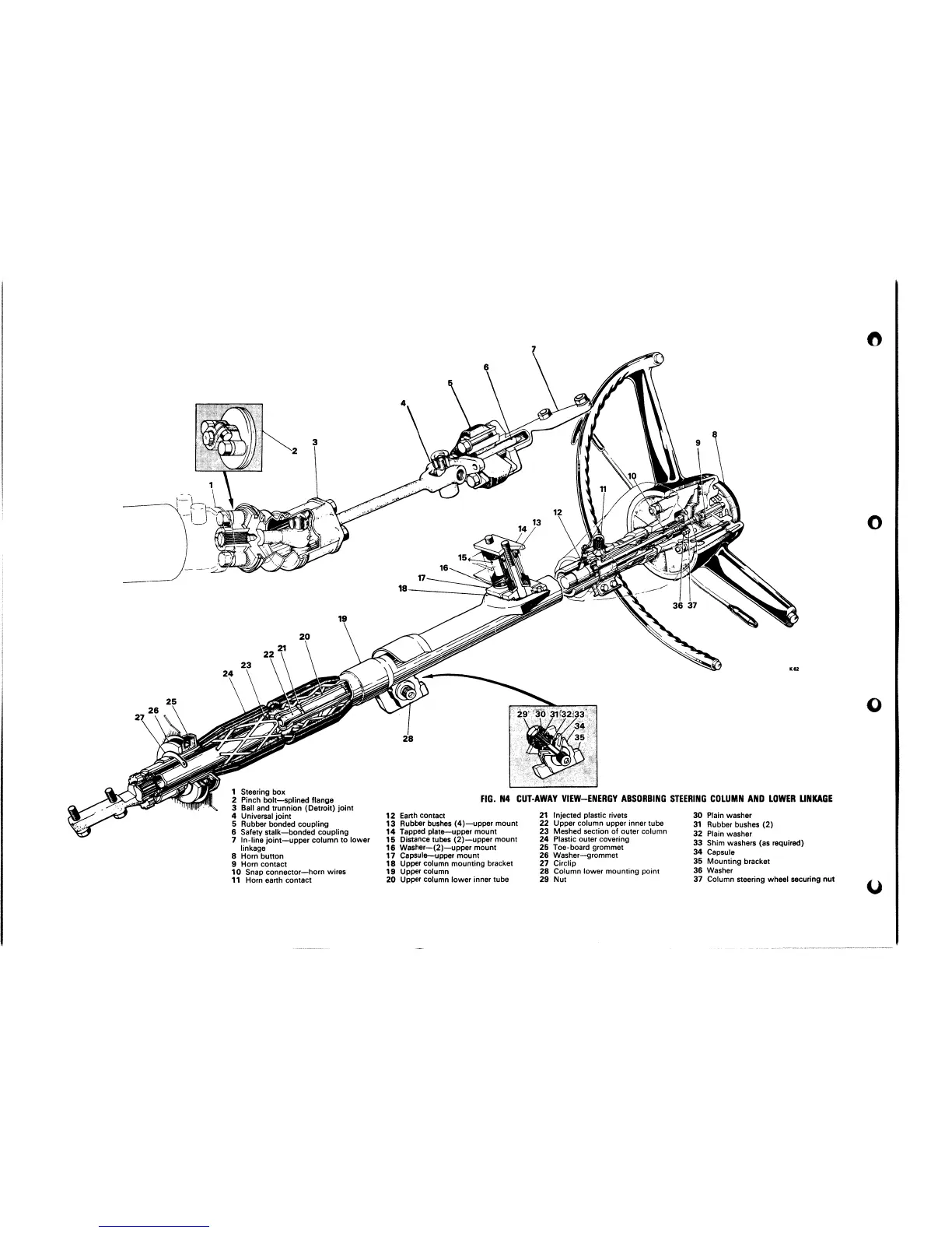
Pinch 6olt-splined flange
FIG. N4 CUT-AWAY VIEW-ENERGY ABSORBING STEERING COLUMN AND LOWER
3
Ball and trunnion (Detroit) joint
30
Plain washer
1
Steerinn box
.
.
unt
23
Meshed section of outer column
33
Plain wachnr
4
Universal joint
12
Earth contact
21
Injected plastic rivets
5
Rubber bonded coupling
13
Rubber bushes (4)-upper mount
22
Upper column upper inner tube
31
Rubber bushes (2)
6
Safety stalk-bonded coupling
14
Tapped plateupper mol
--
.
.-...
..wv,.w.
7
In-line joint-upper column to lower
15
Distance tubes (2)-upper mount
24
-
Plastic outer covering
311
Shim wachnrc lac
rat-
linkage
16
Washer-(2)-upper mol
8
Horn button
17
Capsule--upper mount
26
Washer--grommet
9
Horn contact
18
Upper column mounting
10
Snap connector-horn wires
19
Upper column
11
Horn earth contact
20
Upper column lower innt
Jnt
25
Toe-board grommet
bracket
27
Circlip
35
dunt tin^
bracket
28
Column lower mounting point
36
Washer
31
tube
29
Nut
37
Column steering wheel securing nut
LINKAGE