Workshop
Manual
Rolls-Royce Silver Shadow
8
Bentley
T
Series
Chapter
M
8.
Excessive brush wear can cause damage to the
commutator if the brush leads come into contact with
the running
facr of the cornmutator.
9.
The minimum arceptable length of the brushes
is
8,70
mm.
(
+in.).
It
is
imperative that they are
renewed when near or below this measurement.
--
10.
Generator charging failures can sometimes be
attributed to the brush leads fouling the corners of
the brush boxes, or by a short circuit
between the
brush leads and band cover.
The latter of these faults can occur if the
insulating sleeves have pulled away from their
normal positions, exposing the wires. Always ensure
that the wires are completely covered. The following
information is included to assist generator overhaul
when renewal is impracticable.
Generator-To remove
1.
Slacken the bolts at both ends of the slotted
link to release the tension from the driving belts.
2.
Remove the driving belts.
3.
Disconnect the leads from the rear of the
generator.
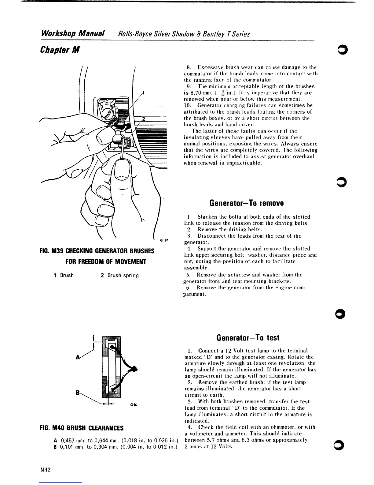
FIG. M39 CHECKING GENERATOR BRUSHES
FOR FREEDOM OF MOVEMENT
4.
Support the generator and remove the slotted
link upper securing bolt, washer, distance piece and
nut, noting the position of. each to facilitate
assembly.
1
Brush
2
Brush spring
5.
Remove the setscrew and washer from the
generator front
6nd rear mounting brackets.
6.
Remove the generator from the engine com-
partment.
Generator-To test
1.
Connect a
12
Volt test lamp to the terminal
markcd
'
D' and to the generator casing. Rotate the
armature slowly through at least one revolution; the
lamp should remain illuminated. If the generator has
an open-circuit the lamp will not illuminate.
2.
Remove the earthed brush; if the test lamp
remains illuminated, the generator has a short
circuit to earth.
3.
With both brushes removed, transfer the test
lead from terminal
9'
to the commutator.
If
the
lamp illuminates, a short circuit in the armature is
indicated.
FIG. M4O BRUSH CLEARANCES
4.
Check the field coil with an ohmmeter, or with
a voltmeter and ammeter. This should indicate
A
0,457
mm.
to
0,644
mm.
(0.01
8
in;
to
0.026 in.)
between
5.7
ohms and
6.3
ohms or approximately
B
0,101
mm.
to
0,304
mm.
(0.004 in.
to
0.012 in.)
2
amps at
12
Volts.