Rolls-Royce Silver Shadow
B
Bentley
T
Series
Workshop
Manual
C
Chapter
M
4.
The voltage should rise steadily and then
drop slightly
a1 the instant of contact closure. The
cut-in voltage is the reading which is indicated
immediately before the pointer drops back and
should occur between the limits given in Chapter A
-
General Information. If the cut-in occurs outside
the limits, an adjustment must be made. In this
event reduce engine speed to below cut-in and
proceed as follows.
5.
Remove the control box cover by removing the
securing screws.
6.
Using the special 'Lucas' tool (543-817-42),
turn the cut-out relay adjustment cam a small amount
in the appropriate direction (turning the tool clock-
wise raises the setting and turning the tool
anti-
clockwise lowers the setting).
7.
Repeat Operation
6
until the correct setting is
obtained.
8.
Switch off the engine, fit the original connec-
tions and the cover.
Drop-off voltage-To ad just
1.
Withdraw the cables from the control box
terminal blades
'
B'.
2.
Connect the first grade Zero to 20 Volt moving
coil voltmeter between the control box terminal
marked
'
B'
and earth.
3.
Start the engine and raise the speed to
approximately
3000 [.p.m.
4.
Slowly decelerate and observe the voltmeter
pointer.
5.
Opening of the contacts (indicated by the volt-
meter pointer falling to Zero) should occur between
the limits given in Chapter A
-
General Information.
If the
drop-off voltage occurs outside these limits
an adjustment must be made as follows.
6.
Stop the engine and remove the control box
cover.
7.
Adjust the drop-off voltage by carefully bending
the fixed contact bracket
(see
Fig.
M46).
Reducing
the contact gap will raise the drop-off voltage and
increasing the gap will lower the drop-off voltage.
8.
Repeat the test and if necessary, adjust until
the correct drop-off setting is obtained.
Note
This should result in a contact follow-
through or blade deflection of between
0,25 mm. to 0,89 mm. (0.010 in. and
0.035
in.)
9.
Fit the original connections and the cover.
Air-gap settings-To adjust
Air gap settings are accurately adjusted during pro-
duction of the control box and should require no
further attention. If the original adjustments have
been disturbed they should be set as follows.
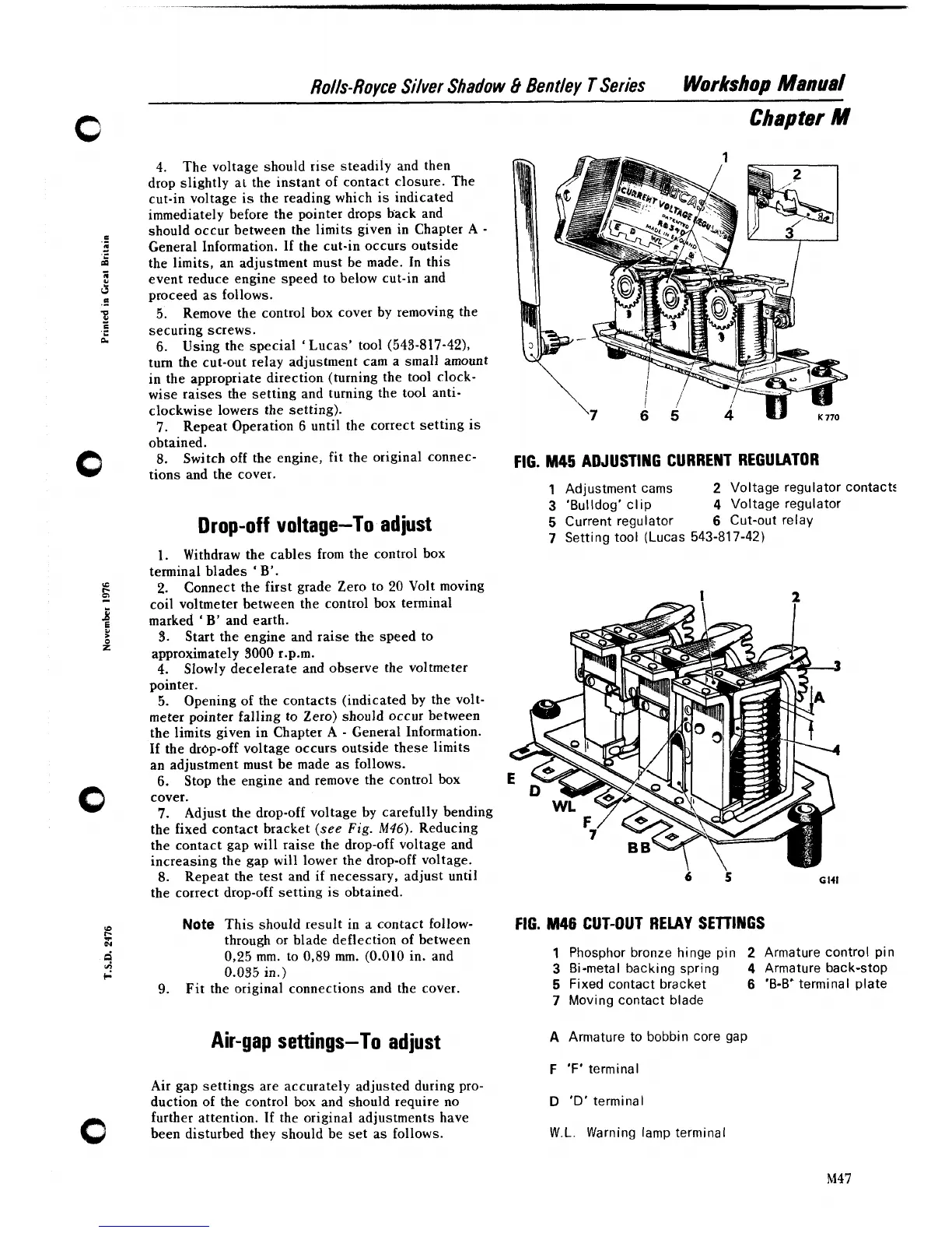
FIG.
M45
ADJUSTING CURRENT REGULATOR
1
Adjustment cams
2
Voltage regulator contacts
3
'Bulldog' clip
4
Voltage regulator
5
Current regulator
6
Cut-out relay
7
Setting tool (Lucas
543-817-42)
FIG.
M46
CUT-OUT RELAY SETTINGS
1
Phosphor bronze hinge pin
2
Armature control pin
3
Bi-metal backing spring
4
Armature back-stop
5
Fixed contact bracket
6
'B-B'
terminal plate
7
Moving contact blade
A
Armature to bobbin core gap
F
'F'
terminal
D
'D' terminal
W.L.
Warning lamp terminal