Workshop
Manual
Rolls Royce Silver
Shadow
8
Bentley
T
Serles
Chapter
N
4.
Tighten the pump driving belts then proceed to
tighten the pulley retaining nut.
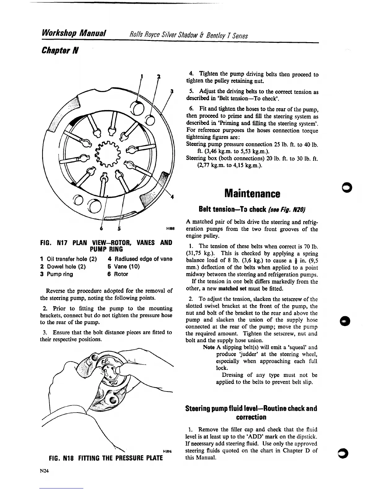
FIG. N17 PLAN VIEW-ROTOR, VANES AND
PUMP
RING
1
Oil transfer hole
(2)
4
Radiused edge of vane
2
Dowel hole
(2)
5
Vane
(1
0)
3
Pump ring
6
Rotor
Reverse the procedure adopted for the removal of
the steering pump, noting the following points.
2.
Prior to fitting the pump to the mounting
brackets, connect but do not tighten the pressure hose
to the rear of the pump.
3. Ensure that the bolt distance pieces are fitted to
their respective positions.
FIG. N18 FllllNG THE PRESSURE PLATE
5.
Adjust the driving belts to the correct tension as
described
in
'Belt tension-To check'.
6.
Fit and tighten the hoses to the rear of the pump,
then proceed to prime and
fill
the steering system as
described
in
'Priming and filling the steering system'.
For reference purposes the hoses connection torque
tightening figures are:
Steering pump pressure connection 25 lb. ft. to 40 lb.
ft.
(3,46 kg.m. to 533 kg.m.).
Steering box (both connections) 20 lb. ft. to 30 lb. ft.
(2,77 kg.m. to 4,15 kg.m.).
Belt tension-To check
(see
Fig.
N20)
A
matched pair of belts drive the steering and refrig-
eration pumps from the two front grooves of the
engine pulley.
1.
The tension of these belts when correct is 70
lb.
(31,75 kg.).
This is checked by applying a spring
balance load of
8
lb. (3,6 kg.) to cause a
8
in. (93
mm.)
deflection of the belts when applied to a point
midway between the steering and refrigeration pumps.
If the tension in one belt differs markedly from the
other, a new matched set must
be
fitted.
2.
To adjust the tension, slacken the setscrew of the
slotted swivel bracket at the front of the pump, the
nut and bolt of the bracket to the rear and above the
pump and slacken the union of the supply hose
connected at the rear of the pump; move the pump
the required amount.
Tighten the setscrew, nut and
bolt and the supply hose union.
Note
A slipping belt(s) will emit a 'squeal' and
produce
'judder' at the steering wheel,
especially when approaching each full
lock.
Dressing of any type must not be
applied to the belts to prevent belt slip.
Steering pump fluid level-Routine cheek and
correction
1.
Remove the filler cap and check that the fluid
level is at least up to the 'ADD' mark on the dipstick.
If necessary add steering fluid. Use only the approved
steering fluids quoted on the chart in Chapter D of
this Manual.